
Components for Determining the Humidity of Items

A technology of components and items, applied in the direction of humidity sensors, applications, instruments, etc., can solve the problems of data cannot be used digitally, cannot be further processed, etc.

Active Publication Date: 2021-07-27
AIT AUSTRIAN INST OF TECH
View PDF0 Cites 0 Cited by
  • Summary
  • Abstract
  • Description
  • Claims
  • Application Information

AI Technical Summary

Problems solved by technology

The determined data are not to be used digitally or further processed

Method used


Image

  • Components for Determining the Humidity of Items
  • Components for Determining the Humidity of Items
  • Components for Determining the Humidity of Items

Examples


Embodiment Construction

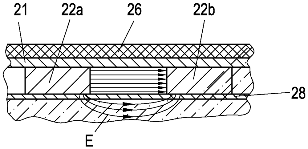
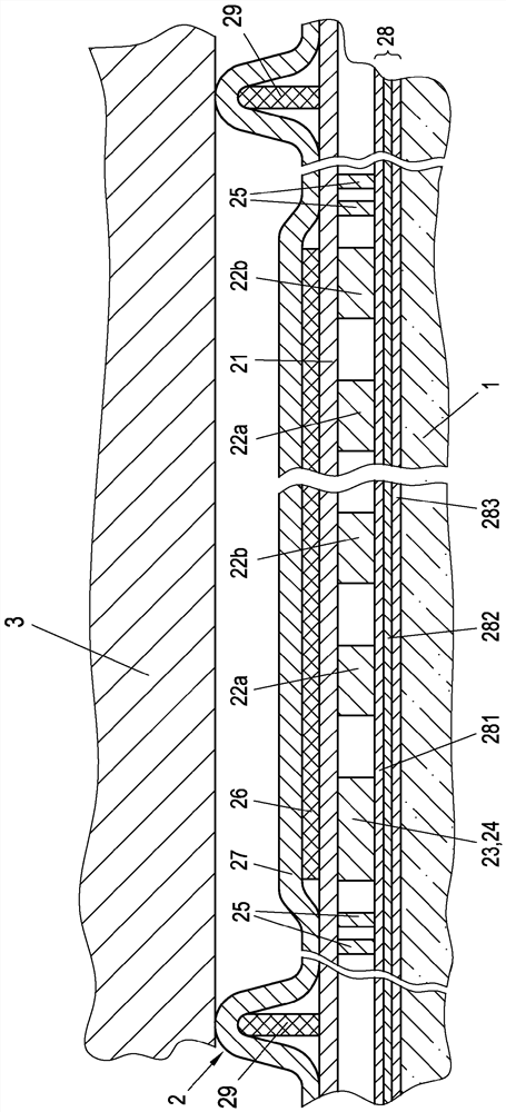
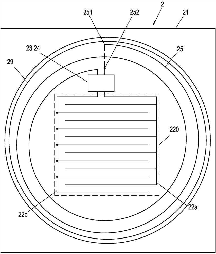
[0031] exist figure 1 The illustrated component 2 for determining the humidity of an object 1 has an electrically insulating carrier layer 21 . At one side of the electrically insulating carrier layer 21 there are two electrodes 22a, 22b, as image 3 The configuration shown in is interdigitated electrodes. In addition, in figure 1 A digital capacitance measurement device 23 is shown in , to which electrodes 22a, 22b are coupled ( image 3 ). An NFC transponder 24 is also arranged in the same chip, for example in the capacitance measuring device 23 , which is coupled to an antenna 25 which is arranged in the peripheral region of the component 2 . The capacitive measuring device 23 and the NFC transponder 24 can also be arranged in separate chips.

[0032] The measurement results of the capacitance measuring device 23 are transmitted to the NFC transponder 24 . If the NFC transponder 24 is queried by an external data communication device via the antenna 25, it triggers the...


PUM

PropertyMeasurementUnit
relative permittivityaaaaaaaaaa

Abstract

The invention relates to an assembly (2) for determining the humidity of an object (1), in particular of human skin, comprising an electrically insulating carrier layer (21) on which the following units are mounted: - at least two electrodes (22a, 22b), in particular interdigitated electrodes, arranged on the first side of the carrier layer (21), - digital capacitance measuring device (23), to which the electrodes (22a, 22b) are coupled, - with antenna The NFC trans-frequency radar transmitter (24) of (25), in order to transmit further via antenna (25) by radio, the measurement result of capacitance measuring device (23) is transmitted to this NFC trans-frequency radar transmitter, wherein, The NFC transponder (24) and the capacitance measuring device (23) are in particular arranged on the same chip, and the shield (26) is located on the side of the carrier layer (21) opposite the first side And in particular to the system ground of the capacitance measuring device ( 23 ).

Description

technical field [0001] The invention relates to an assembly for determining the humidity of an item, in particular of human skin. Background technique [0002] Various skin moisture measuring devices are known from the prior art, all of which have certain disadvantages. It is particularly difficult in the case of these moisture measuring devices to obtain unbiased measured values ​​in each case from the same area of ​​the skin in a simple manner without contact. Furthermore, although measurements can be carried out under laboratory conditions in the table-top devices known from the prior art, the table-top devices are not mobile. In the case of the impedance method, a galvanic skin contact and thus a voltage supply are required. The determined data cannot be used digitally or processed further. Contents of the invention [0003] The present invention aims to solve these problems. [0004] The invention achieves this object by means of an assembly for determining the hu...

Claims


Application Information

Patent Timeline
Patent Type & Authority Patents(China)
IPC IPC(8): G01N27/22A61B5/00
CPCA61B5/443A61B2562/029G01N27/223A61B5/441G01N33/4833
Inventor A.奥伯雷特纳R.鲁夫
Owner AIT AUSTRIAN INST OF TECH
Learn More