
Feeding device for sponge foaming machine

A foaming machine and sponge technology, applied in the field of machinery, can solve the problems of manpower splashing, easily damaged foaming machine, iron filings inclusion, etc., to improve processing quality and efficiency, improve automatic production, and avoid clogging problems

Inactive Publication Date: 2017-12-08
苏州恒昇海绵机械制造有限公司
View PDF8 Cites 2 Cited by
  • Summary
  • Abstract
  • Description
  • Claims
  • Application Information

AI Technical Summary

Problems solved by technology

[0002] With the development of polyurethane foam foaming technology, the demand for sponge products is increasing. With the maturity of the industry, the competition in the sponge market is becoming increasingly fierce. Sponge manufacturers can only adapt to it by improving production efficiency and reducing labor costs. Market competition, in the foaming process of the sponge, it is necessary to pour the mixed polyurethane, foaming agent and other mixture into the foaming mold, the barrel containing the liquid is relatively large, and it is often spilled or not cleaned by manpower , and requires a large labor cost; at the same time, iron filings are likely to be included in the sponge foaming raw material during the production process, which not only affects the production quality of the sponge, but also easily damages the foaming machine, and is not conducive to the automation of the foaming machine

Method used


Image

  • Feeding device for sponge foaming machine

Examples


Embodiment Construction

[0013] Combine below figure 1 And further illustrate the technical solution of the present invention through specific examples.

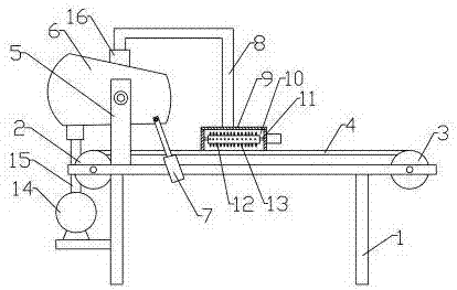
[0014] A feeding device for a sponge foaming machine, comprising: a basic support 1, a driving roller 2 and a passive roller 3, the driving roller 2 and the passive roller 3 are respectively arranged at the two ends of the basic support 1, and the driving roller 2 and the The passive roller 3 is covered with an endless conveyor belt 4 for transmission connection, and the material to be foamed is poured into the endless conveyor belt for transportation.

[0015] One side of the driving drum 2 is provided with a support rod 5 located on the base support 1, and the support rod 5 is hingedly provided with a bucket 6, and one end of the bucket 6 is hinged with a telescopic device 7 located on the base support 1, Drive bucket 6 to carry out angle adjustment, is convenient to unloading.

[0016] The top of the feed barrel 6 is provided with a feed pipe 8...


PUM


Abstract

The invention discloses a feeding device for a sponge foaming machine. The feeding device comprises a foundation support, a driving roller and a driven roller. The driving roller and the driven roller are correspondingly arranged at the two ends of the foundation support. The driving roller and the driven roller are sleeved with an annular conveying belt for transmission connection. The feeding device is characterized in that a support rod located on the foundation support is arranged on one side of the driving roller, a material cylinder is hinged to the support rod, and a first telescopic device located on the foundation support is hinged to one end of the material cylinder; and a feeding pipe is arranged on the top of the material cylinder, a material box located above the annular conveying belt is connected to the feeding end of the feeding pipe, and an iron removal device is arranged in the material box. According to the feeding device for the sponge foaming machine, the feeding angle of the material cylinder is adjusted through the telescopic device, discharging is facilitated, discharging is continuous and stable in the material cylinder, and the blocking problem is avoided; and besides the on-line iron removal function is achieved, and the machining quality and efficiency of sponge are improved.

Description

technical field [0001] The invention relates to the technical field of machinery, in particular to a feeding device for a sponge foaming machine. Background technique [0002] With the development of polyurethane foam foaming technology, the demand for finished sponge products is increasing. With the maturity of the industry, the competition in the sponge market is becoming increasingly fierce. Sponge manufacturers can only adapt to it by improving production efficiency and reducing labor costs. Market competition, in the foaming process of the sponge, it is necessary to pour the mixed polyurethane, foaming agent and other mixture into the foaming mold, and the barrel containing the liquid is relatively large, and it is often spilled or not cleaned by manpower. , and requires a large labor cost; at the same time, iron filings are likely to be included in the sponge foaming raw material during the production process, which not only affects the production quality of the sponge...

Claims


Application Information

Patent Timeline
Patent Type & Authority Applications(China)
IPC IPC(8): B29C44/38B29C44/34B03C1/18
CPCB29C44/38B03C1/18B29C44/3442B29C44/35
Inventor 刘正奎
Owner 苏州恒昇海绵机械制造有限公司
Learn More