Radar antenna array on rear side of automobile and antenna area array

A radar antenna and antenna array technology, applied in the field of antennas, can solve the problems of large feeder loss, low precision, narrow bandwidth, etc., to meet the needs of detection power, ensure the accuracy of angle measurement, and the effect of wide working bandwidth

Pending Publication Date: 2017-12-08
HUIZHOU DESAY SV AUTOMOTIVE
View PDF9 Cites 12 Cited by
  • Summary
  • Abstract
  • Description
  • Claims
  • Application Information

AI Technical Summary

Problems solved by technology

[0005] 1. Although the series-fed resonant antenna has a compact structure, it also has the disadvantage of narrow bandwidth.
Although parallel feed can achieve wider bandwidth, it also has the disadvantages of large feeder loss and relatively large size
[0006] 2. If the power coverage of the side and rear vehicle anti-collision radar system is not ideal enough, in addition to useful signals, some unnecessary clutter signals will enter the system, increasing the difficulty of back-end signal processing
[0007] 3. For the target detection of the vehicle anti-collision radar system, in addition to the speed and distance, the target orientation is also a key indicator. If the single-baseline angle measurement scheme is used, only a small spacing method can be used. This method has a negative impact on the system hardware. Disadvantages of high index requirements and relatively low precision

Method used


Image

  • Radar antenna array on rear side of automobile and antenna area array
  • Radar antenna array on rear side of automobile and antenna area array
  • Radar antenna array on rear side of automobile and antenna area array

Examples


Embodiment 1

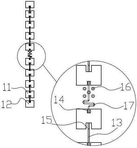
[0034] This embodiment provides an antenna array, which is applied to the rear side of the automobile radar and is a component of the radar antenna array on the rear side of the automobile. Since the direction detected by the radar on the rear side of the automobile has a strong directivity, the radar range The shape needs to be more precise. As the basic unit of the antenna array, it needs to have the characteristics of low sidelobe and wide bandwidth, such as figure 1 shown. It includes a plurality of first antenna units 11 and a feeding structure. Wherein, both the first antenna unit 11 and the second antenna unit 12 are square sheet structures, which may be composed of copper clad layers. In terms of arrangement, a plurality of first antenna units 11 are arranged in a line to form a line array. The feeding connection between each first antenna unit 11 is realized through a microstrip 13 . Finally, the feeding is performed through the feeding structure arranged at the c...

Embodiment 2

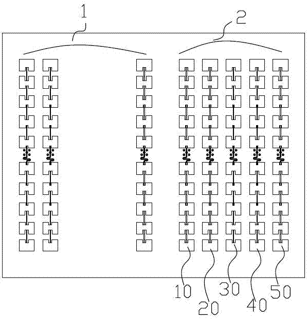
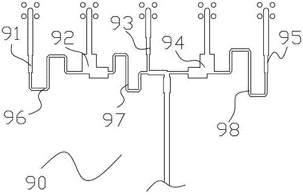
[0044] This embodiment also provides a radar antenna area array on the side and rear of the vehicle, which can mainly realize functions such as blind spot detection, lane change assistance, and RCTA. like figure 2 and image 3 shown. It includes a transmitting antenna unit 1 and a receiving antenna unit 2 . Specifically, it includes a plurality of in-line antenna arrays arranged on the first surface of the circuit board and a feeding network 90 arranged on the second surface of the circuit board.

[0045] Both the transmitting antenna unit 1 and the receiving antenna unit 2 are composed of a plurality of in-line antenna arrays.

[0046] In terms of the transmitting antenna part 1, it includes five in-line antenna arrays arranged in parallel, and the distance between each in-line antenna array is half of the wavelength, finally forming a transmitting antenna array.

[0047] In addition, in terms of the feeding circuit of the transmitting antenna unit 1, it is composed of c...

Embodiment 3

[0054] The difference between this embodiment and embodiment 2 is that, as figure 2 As shown, the receiving antenna unit 2 in this embodiment includes a sixth in-line antenna array 60 , a seventh in-line antenna array 70 and an eighth in-line antenna array 80 arranged in parallel. Wherein, the distance between the sixth in-line antenna array 60 and the seventh in-line antenna array 70 is 0.5 times of the working wavelength. The distance between the seventh in-line antenna array 70 and the eighth in-line antenna array 80 is 2.5 times of the working wavelength. The receiving antenna part 2 forms a 3-antenna scheme with long and short baselines to ensure accurate angle measurement with high precision.

[0055] In terms of the feeding network of the receiving antenna part 2, it is specifically fed through a separate feeding microstrip line, that is, three microstrips directly connected to the feeding source are used to feed the sixth in-line antenna array 60 and the seventh in-l...


PUM


Abstract

The invention relates to a radar antenna array on the rear side of an automobile. The radar antenna array comprises multiple first antenna units and a feed structure; the multiple first antenna units are form a horizontal-line-shaped array, and connected through microstrips; the feed structure is arranged in the symmetrical centre of the multiple antenna units; a first groove is formed in the front end of each antenna unit while a second groove is formed in the back end; and multiple in-line arrangement type antenna arrays form an antenna area array with a transmitting antenna part and a receiving antenna part. The radar antenna array has the beneficial effects as follows: 1) by virtue of the adopted traveling wave string feed microstrip array, the radar antenna array can be higher in working bandwidth and compact in structure and can be integrated to a sensor easily; 2) the detection capability of the transmitting directional diagram is optimized based approximate super-cosecant-squared distribution; high gain is realized in a position where far distance detection is needed while the gain is lowered in a position where far distance detection is not needed, so that requirement of the radar system on the detection capability can be better satisfied; and 3) by virtue of a receiving antenna scheme of three antennas with long and short base lines, enough measurement angle precision can be ensured.

Description

technical field [0001] The invention relates to the technical field of antennas, in particular to a radar antenna array and an antenna array at the side and rear of a car. Background technique [0002] The anti-collision function at the side and rear of the car is to detect obstacles in the area behind the side and provide early warning to help the driver take emergency measures. [0003] The side and rear collision avoidance functions mainly include blind spot detection, lane change assistance, RCTA and other functions. Because of its low cost and low profile, the microstrip antenna is especially suitable for automotive microwave radar. In order to save size and reduce loss, the array is usually formed in the form of series feed, but the commonly used series feed antenna is a resonant antenna, which has the disadvantage of narrow bandwidth. If RO4350 plate is used, the thickness is 0.254mm, and the dielectric constant is 3.66. At this time, a single multi-element antenna ...

Claims


Application Information

Patent Timeline
Patent Type & Authority Applications(China)
IPC IPC(8): H01Q1/50H01Q21/00
CPCH01Q1/50H01Q21/00
Inventor 高金瑞周立夫
Owner HUIZHOU DESAY SV AUTOMOTIVE
Why Eureka
Try Eureka