
A non-imaging type satellite-borne laser warning system

A laser warning and non-imaging technology, applied in beacon systems using electromagnetic waves, optical radiation measurement, spectrometry/spectrophotometry/monochromator, etc., can solve the problem of affecting positioning accuracy, inconsistent response time, and power consumption and cost increase, etc., to achieve the effect of wide spectral detection range, fast system response speed, and reduced quality

Active Publication Date: 2017-12-12
NANJING UNIV OF SCI & TECH
View PDF7 Cites 4 Cited by
  • Summary
  • Abstract
  • Description
  • Claims
  • Application Information

AI Technical Summary

Problems solved by technology

Although the technology of CCD imaging alarm system is mature, there are still many disadvantages and deficiencies. For example, CCD outputs in scanning mode, the frame frequency is not high, and the response speed is slow. For the alarm system, the system response time is particularly important. Determine the success or failure of the whole system, the CCD output image has relatively high power consumption and requirements for subsequent processing circuits
The size and response time of the CCD pixels are inconsistent, which will affect the measurement accuracy of the spot, and then affect the positioning accuracy
Different spectral ranges require different CCD image sensors. To detect threatening lasers from visible light to far infrared, a combination of multiple CCDs is required, which not only complicates the optical system and peripheral drive circuits, but also causes the entire The power consumption and cost of the system are greatly increased, the volume is large, heavy, the false alarm rate is high, and the detection spectrum range is narrow

Method used


Image

  • A non-imaging type satellite-borne laser warning system
  • A non-imaging type satellite-borne laser warning system
  • A non-imaging type satellite-borne laser warning system

Examples


Embodiment Construction

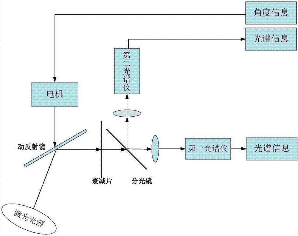
[0014] The invention is a non-imaging space-borne laser warning system, which includes two parts: spectral analysis of the target laser to be measured, azimuth determination and alarm of the target laser to be measured. Such as figure 1 As shown, it is the spectral analysis system of the non-imaging spaceborne laser warning system of the present invention. The spectral analysis system is composed of a movable reflector, an attenuation sheet, a beam splitter, a first spectrometer, a second spectrometer and a motor, and the motor is connected to the movable reflector. The attenuator is set between the movable reflector and the beam splitter, the motor controls and rotates the movable reflector to adjust the incident angle of the target laser, so that the target laser passes through the attenuator, passes through the beam splitter and is divided into two laser beams, and the two laser beams pass through The first spectrometer enters the first spectrometer through the lens, and th...


PUM


Abstract

The invention provides a non-imaging type satellite-borne laser warning system comprising a spectral analysis system and a positioning system. The spectral analysis system consists of a moving reflector, an attenuation sheet, a light splitter, a first spectrograph, a second spectrograph and a motor. The motor is connected with the moving reflector; the attenuation sheet is arranged between the moving reflector and the light splitter; the motor controls and rotates the moving reflector to adjust the angle of incidence of target laser so that the target laser penetrates the attenuation sheet and is split into two paths of laser; one path penetrates a lens to enter the first spectrograph and the other path penetrates a lens to enter the second spectrograph; the first spectrograph and the second spectrograph analyze the spectral range of the target laser. The system can detect to-be-tested laser on the ground and provide accurate spectral information and laser source orientation of to-be-tested laser, thereby achieving warning of to-be-tested laser.

Description

technical field [0001] The invention belongs to the field of laser warning, in particular to a non-imaging spaceborne laser warning system. Background technique [0002] Nowadays, the imaging spaceborne laser warning system is mainly CCD imaging type, and the orientation of the target laser is determined by imaging the position of the CCD target surface. Although the technology of CCD imaging alarm system is mature, there are still many disadvantages and deficiencies. For example, CCD outputs in scanning mode, the frame frequency is not high, and the response speed is slow. For the alarm system, the system response time is particularly important. Determine the success or failure of the entire system, the CCD output image has relatively high power consumption and requirements for subsequent processing circuits. The size and response time of the CCD pixels are inconsistent, which will affect the measurement accuracy of the light spot, and then affect the positioning accuracy....

Claims


Application Information

Patent Timeline
Patent Type & Authority Applications(China)
IPC IPC(8): G01J3/02G01J3/28G01S1/70
CPCG01J3/0208G01J3/0213G01J3/28G01S1/70
Inventor 钱惟贤高青松蔡贵霞陈钱顾国华顾芷西杨锦清李之秀
Owner NANJING UNIV OF SCI & TECH
Learn More