An energy-saving metal strip rolling mill and rolling method

An energy-saving technology for metal strips, applied in the direction of metal rolling, metal rolling, and driving devices for metal rolling mills, can solve the problems of small cumulative reduction rate in a single rolling process, high unit energy consumption, and thinning capacity. Limited and other problems, to achieve the effect of reducing the number of rolling passes and intermediate annealing times, the cumulative reduction rate is large, and the reduction amount of each pass is large

Active Publication Date: 2019-07-23
宁波中瑞新材料有限公司
View PDF7 Cites 0 Cited by
  • Summary
  • Abstract
  • Description
  • Claims
  • Application Information

AI Technical Summary

Problems solved by technology

There is an uncoiler in front of the rolling mill (unit), and the rolled piece between the entrance of the rolling mill (unit) and the uncoiler has back tension; under the action of the back tension, the motor of the uncoiler can be in a power generation state, but the The electricity generated by the unwinding motor cannot be used
In addition, the drive motors of the upper and lower work rolls of this type of synchronous rolling mill adopt load balancing control, and the main drive motor does not have the ability to generate electricity
This type of rolling mill has large working roll diameter, large rolling force and high unit energy consumption
Limited rolling capacity, small cumulative reduction rate in a single rolling pass, many intermediate annealing passes, and high energy consumption

Method used


Image

  • An energy-saving metal strip rolling mill and rolling method
  • An energy-saving metal strip rolling mill and rolling method
  • An energy-saving metal strip rolling mill and rolling method

Examples


Embodiment Construction

[0043] The present invention will be further described in detail below in conjunction with the accompanying drawings and specific embodiments.

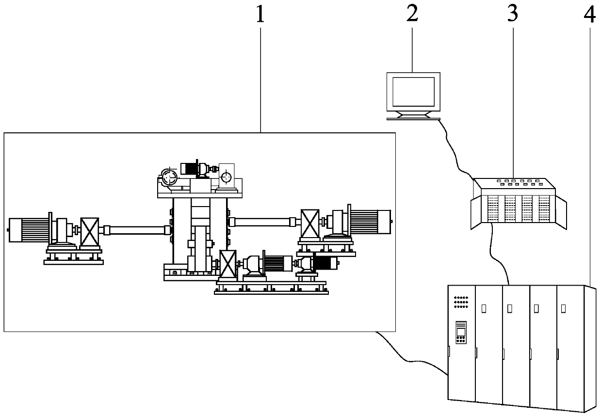
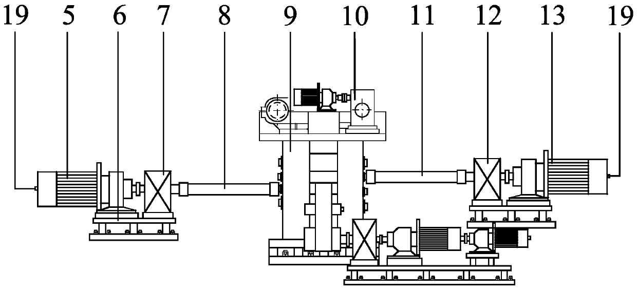
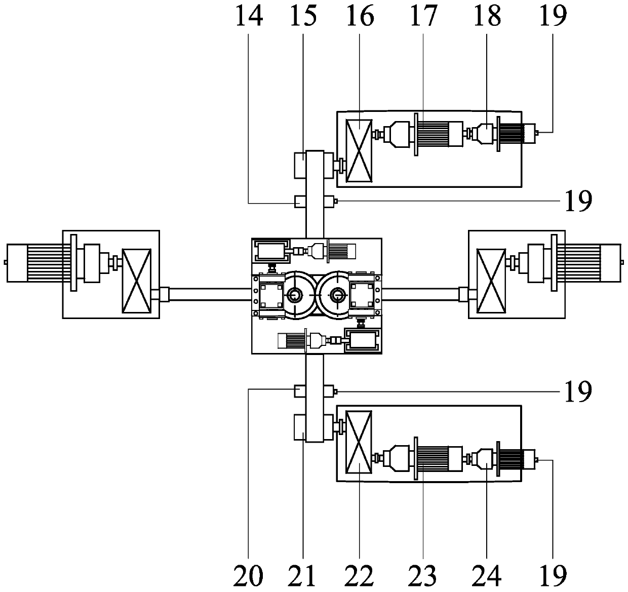
[0044] In this embodiment, the structural diagram of the rolling mill is shown in figure 1 , the structural diagram of the mechanical part of the rolling mill is shown in figure 2 , image 3 , Figure 4 with Figure 5 , see the content of the invention for the specific structure. Both the main drive motor and the take-up motor use 4-fold frequency motors, and the coiling and rewinding adopt the form of double take-up motors in series, and the main drive motor and the take-up motor are driven by a common DC bus multi-machine drive four-quadrant inverter. The coiling tension is divided into three gears, the range of the high tension gear is 50-80kN, the middle tension gear is 20-50kN, and the small tension gear is 3-20kN. The rolled piece is 304 stainless steel, the initial thickness of the rolled piece is 1.0mm, the width is 450m...


PUM


Abstract

Provided are an energy-saving metal strip rolling mill and a rolling method. The rolling mill comprises a mechanical part and a control part; the rolling mill adopts working rolls on two sides to drive, and the speeds of the upper working roll and the lower working roll are controlled separately; a rolled piece can bear a compression-shearing-stretching combined forming effect, the rolling thinning capacity of the rolling mill is high, the pass rolling rate and the accumulated rolling rate are high, the rolling pass and the intermediate annealing number can be effectively reduced, and the energy-saving effect is good; a large motor and a small motor which are in series connection are used for both coiling and rolling, the tension force is divided into three gears including large, middle and small, the tension gear is selected according to the target tension, the overall loads of the coiling motors are increased, the motor efficiency is improved, and the motor is more energy-saving; main transmission motors and the coiling motors are all large-frequency doubling alternative current motors, the load ranges of the motors are large, the efficiency is high, and the motors are more energy-saving; a common direct current bus multi-drive transmission four-quadrant frequency changer is adopted for driving of the motors, a part of the motors are in a generating state in rolling, and generated power can be provided for other motors, so that the energy-saving effect is improved.

Description

technical field [0001] The invention belongs to the technical field of metal strip rolling, in particular to an energy-saving metal strip rolling mill and a rolling method. Background technique [0002] With the development of the economy and the improvement of people's living standards, everyone's requirements for the environment are getting higher and higher. In order to get rid of the low-efficiency and extensive development model, the country has proposed a sustainable development strategy, vigorously promoting energy conservation and emission reduction, in order to solve the contradiction between economic development and environmental pollution. [0003] As a high-energy-consuming industry, the metal rolling industry is one of the key industries to be rectified by the state, and the pressure on energy conservation and emission reduction is very high. [0004] In addition, the previous disorderly and crazy expansion of production capacity has also intensified the compet...

Claims


Application Information

Patent Timeline
Patent Type & Authority Patents(China)
IPC IPC(8): B21B35/00B21B37/52
CPCB21B35/00B21B37/52
Inventor 孙祥坤饶钦玉赵启林付华高刘相华
Owner 宁波中瑞新材料有限公司
Why Eureka
Try Eureka