Single pendulous vertical type flat-pressing flat-die-cutting machine

The technology of flat pressing and die cutting machine is applied in the field of single pendulum vertical flat pressing flat die cutting machine, which can solve the problems of high production cost, low production efficiency, low degree of automation, etc., so as to improve production and processing efficiency. , reduce labor costs, improve the effect of automation

Inactive Publication Date: 2017-12-15
成都佳欣诚信科技有限公司
View PDF0 Cites 8 Cited by
  • Summary
  • Abstract
  • Description
  • Claims
  • Application Information

AI Technical Summary

Problems solved by technology

Usually the die-cutting and creasing process is to combine the die-cutting knife and the creasing knife in the same template, and perform die-cutting and creasing processing on the die-cutting machine at the same time. Cutting, indentation, flat die cutting machine uses steel knife, metal mold, steel wire, through the stamping between the pressure die and the pressure die, that is, the pressure die is fixed on the workbench, and the pressure die moves up and down For the sheet, the traditional die-cutting machine manually cuts the sheet or paper into sections to form a semi-finished product. The structure of the semi-finished product is wrapped in the waste material, and then the waste material and the finished product are separated manually. Due to the low degree of automation , so that the production efficiency is greatly reduced, and as the labor cost rises, the production cost of the enterprise remains high. Die cutting is used to cut printed products or plates into certain shapes

Method used


Image

  • Single pendulous vertical type flat-pressing flat-die-cutting machine

Examples


Embodiment 1

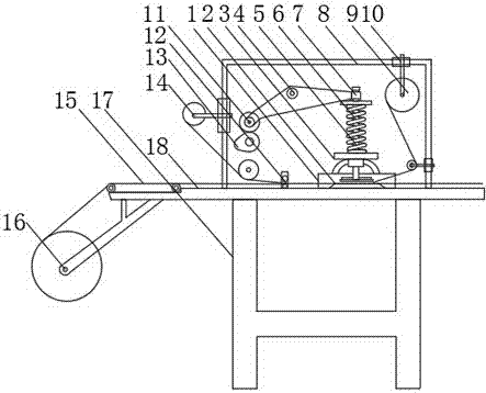
[0023] combined with figure 1 As shown, a single pendulum vertical flat die-cutting machine includes a workbench 18 and a frame 17, the workbench 18 is integrally connected with the frame 17, and the workbench 18 is provided with a frame 17 The opposite side is fixed with a casing 8, and the casing 8 is fixed with a film cylinder 14 perpendicular to any side of the work, and a transmission belt 15 is arranged on the workbench 18 on the same side as the film cylinder 14, and the transmission belt 15 The workbench 18 at the lower end is provided with a feed shaft 16; the inside of the frame 17 is provided with a cam 13, and the cam 13 is transmission-connected with a roller 11, and the roller 11 is fixedly connected with a crank that is fixed on the shell 8 and can swing 4. The other end of the crank 4 is provided with a bump 7, and the workbench 18 is provided with a support frame 1 vertically facing the bump 7, and a vertical bearing 3 is installed on the support frame 1, and ...

Embodiment 2

[0027] In order to make the laminating machine compact in structure, have a strong sense of space, and facilitate the installation and layout of components, on the basis of the structure and principle of Embodiment 1, further combined with the attached figure 1 As shown, the housing 8 of the die-cutting machine in this embodiment is rectangular in shape, and the housing 8 is respectively provided with openings on the side facing the conveyor belt 15 and on the side facing the guide wheels.

[0028] Structural principles:

[0029] The rectangular shell 8 is fixed on the workbench 18, the four sides of the rectangle are vertical to the workbench 18, the opening towards the conveyor belt 15 is the feed port, the opening towards the guide wheel is the discharge port, the outer wall of the rectangular shell 8 is flat, The space formed by the inner wall is simple and tidy. The film roller 14 is fixed on the shell 8 directly above the feed inlet, and the take-up shaft 9 is arranged p...

Embodiment 3

[0031] In order to make the feeding and cutting process of the die-cutting machine smoother, on the basis of the structure and principle of Embodiment 1, further combine the attached figure 1 As shown, in this embodiment, the transmission belt 15 is located above the feed shaft 16 , the crank 4 is provided with a bearing, and a fixed shaft is provided in the bearing, and one end of the fixed shaft is fixed on the casing 8 .

[0032] Structural principles:

[0033] The material to be coated surrounds the conveyor belt 15 from the feed shaft 16 at the lower end of the conveyor belt 15, and the beginning of the conveyor belt 15 is always in contact with the material to be coated, so that the material to be coated is continuously transmitted, and the casing 8 The internal crank 4 is fixed with the housing 8 through the bearing and the fixed shaft, so that the crank 4 rotates on the fixed shaft through the bearing, and the pressing force applied by the cam 13 to the roller 11 is co...


PUM


Abstract

The invention discloses a single pendulum vertical flat die-cutting machine, which comprises a workbench and a frame, the workbench and the frame are integrally connected, and the side of the workbench opposite to the machine frame is fixed There is a casing, and the casing is fixed with a film roller perpendicular to any side of the work, and a conveyor belt is arranged on the workbench on the same side as the film roller, and a feed shaft is arranged on the workbench at the lower end of the conveyor belt; the casing There is a cam structure inside, and a high-strength spring is set on the pressing bar. The rotating cam presses the beer knife on the pressing bar with the beer table through the crank. After pressing, the spring on the pressing bar bounces the pressing bar, and the beer knife Separated from the beer table, the die-cutting process is realized in sequence. The device has a simple structure and is easy to maintain. It is equipped with a conveyor belt for automatic feeding and a receiving shaft for collecting waste. It has a high degree of automation, can save labor costs, and improve production efficiency.

Description

technical field [0001] The invention relates to the field of packaging processing, in particular to a single-pendulum vertical flat-press die-cutting machine. Background technique [0002] The working principle of the die-cutting machine is to use a die-cutting knife, a steel knife, a metal mold, and a steel wire to apply a certain pressure through the embossing plate to cut the printed matter or cardboard into a certain shape. If the entire printed product is cut into a single graphic product, it is called die-cutting; if the steel wire is used to press the mark on the printed product or leave a bent groove, it is called indentation; Heating to a certain temperature, hot stamping a pattern or font with a three-dimensional effect on the surface of the printed product is called hot stamping; if one substrate is used to laminate another substrate, it is called lamination; the rest of the parts except the genuine product are called Waste discharge; Die-cutting process is the m...

Claims


Application Information

Patent Timeline
Patent Type & Authority Applications(China)
IPC IPC(8): B26F1/40B26D5/14B26D5/16B26D7/18B65H20/06
CPCB26F1/40B26D5/14B26D5/16B26D7/1836B65H20/06
Inventor 何秀芳
Owner 成都佳欣诚信科技有限公司
Why Eureka
Try Eureka