Production method of canal tee prefabricated part

A production method and technology for prefabricated parts, applied in the direction of manufacturing tools, auxiliary parts of moulds, mould fixing devices, etc., can solve the problems of many steps in the process of prefabricated parts of canal corners, not being able to make maximum use of water sources, wasting labor and working time, etc. Achieve the effect of improving alkali-resistant aggregate reaction performance, inhibiting alkali-aggregate reaction, and improving work efficiency

Pending Publication Date: 2017-12-15
潘春光
View PDF10 Cites 1 Cited by
  • Summary
  • Abstract
  • Description
  • Claims
  • Application Information

AI Technical Summary

Problems solved by technology

[0009] The deficiencies in the prior art are: 1. The construction period is long, the cost is high, and a lot of labor is required. During the construction period, it is easily affected by the weather, and a large construction site needs to be excavated. It is easily damaged, difficult to maintain, and cannot Reuse, demolition is quite troublesome, and it is easy to damage the original land environment; 2. The water channel channel is easily squeezed, deformed or damaged by the pressure of the soil layer, which not only greatly affects the service life of the beam channel, but also greatly increases the cost input and wastes Resources; 3. When installing butt joints of water canals, the joints are poorly sealed and prone to water leakage, resulting in failure to maximize the use of water sources; 4. There are many steps in the production of prefabricated corners of canals, and it is too cumbersome to take molds, which is a great waste Labor and working hours, low work efficiency

Method used


Image

  • Production method of canal tee prefabricated part
  • Production method of canal tee prefabricated part
  • Production method of canal tee prefabricated part

Examples


Embodiment 1

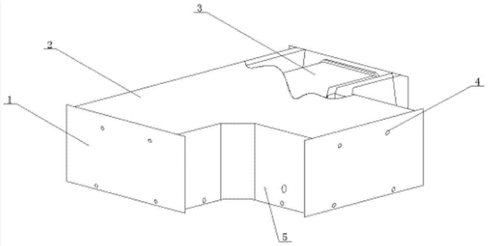
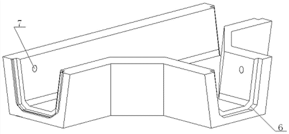
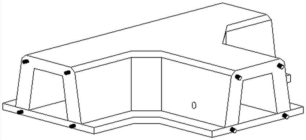
[0051] see Figures 1 to 6 Shown, a kind of production method of drain tee prefabricated part, described method comprises the following steps:

[0052] (1) Design the pouring mold required for the corresponding shape of the prefabricated part of the water channel tee;

[0053] (2) Evenly apply release oil or pad plastic film on the inside of the mold;

[0054] (3) Fix the mold cavity, put on the side wall mold, install the end cover molds at both ends, put in the steel structure to enhance the corner strength of the water channel, put it on the mold cavity, and fix the steel structure; the steel structure is at the bottom There are two layers of distributed steel bars to enhance the force-bearing capacity of the bottom, and use longitudinal tension bars to connect a single U-shaped steel bar member into a whole steel bar structure. Through the anti-extrusion ability of prefabricated parts, the stability of the overall structure is improved, and it is resistant to falling and...

Embodiment 2

[0072] see Figures 1 to 6 Shown, a kind of production method of drain tee prefabricated part, described method comprises the following steps:

[0073] (1) Design the pouring mold required for the corresponding shape of the prefabricated part of the water channel tee;

[0074] (2) Evenly apply release oil or pad plastic film on the inside of the mold;

[0075] (3) Fix the mold cavity, put on the side wall mold, install the end cover molds at both ends, put in the steel structure to enhance the corner strength of the water channel, put it on the mold cavity, and fix the steel structure; the steel structure is at the bottom There are two layers of distributed steel bars to enhance the force-bearing capacity of the bottom, and use longitudinal tension bars to connect a single U-shaped steel bar member into a whole steel bar structure. Through the anti-extrusion ability of prefabricated parts, the stability of the overall structure is improved, and it is resistant to falling and...

Embodiment 3

[0093] see Figures 1 to 6 Shown, a kind of production method of drain tee prefabricated part, described method comprises the following steps:

[0094] (1) Design the pouring mold required for the corresponding shape of the prefabricated part of the water channel tee;

[0095] (2) Evenly apply release oil or pad plastic film on the inside of the mold;

[0096] (3) Fix the mold cavity, put on the side wall mold, install the end cover molds at both ends, put in the steel structure to enhance the corner strength of the water channel, put it on the mold cavity, and fix the steel structure; the steel structure is at the bottom There are two layers of distributed steel bars to enhance the force-bearing capacity of the bottom, and use longitudinal tension bars to connect a single U-shaped steel bar member into a whole steel bar structure. Through the anti-extrusion ability of prefabricated parts, the stability of the overall structure is improved, and it is resistant to falling and...


PUM

PropertyMeasurementUnit
particle sizeaaaaaaaaaa

Abstract

The invention discloses a production method of a canal tee prefabricated part. The production method comprises the steps that (1) a required pouring mold with the corresponding shape of the canal tee prefabricated part is designed; (2) the inner side of the mold is uniformly smeared with demolding oil or a plastic film is put on the inner side of the mold; (3) a mold cavity is fixed, side wall molds sleeve the mold cavity, end cover molds at the two ends are mounted, and a rebar structure which strengthens the canal corner strength is put and is arranged on the mold cavity in a sleeving manner; (4) concrete required by pouring is manufactured on site, concrete is poured into the mold from the middle of the bottom of the mold, vibration is carried out for 1 min to 3 min through a vibrator, the upper surface of the mold is finished, and a mold cover plate is closed; and (5) the canal prefabricated parts subjected to concrete pouring are maintained on site, the side molds of the mold are disassembled after the time.temperature of maintenance is larger than 500 h.DEG C, the mold cavity is disassembled after the time.temperature of watering maintenance is larger than 1500 h.DEG C, after the mold cavity is disassembled, the prefabricated parts are stacked concentratedly, and the prefabricated parts are discharged and utilized after time.temperature of maintenance is larger than 2000 h.DEG C. The production method has the characteristic that construction efficiency can be greatly improved.

Description

technical field [0001] The invention relates to the field of water conservancy engineering, in particular to a production method of a water channel tee prefabricated part. Background technique [0002] Canals are the main tools for irrigation and drainage projects such as farmland water conservancy, transportation, municipal administration, sewage, and drainage in rainy days, and precast concrete U-shaped channel molds are one of the main tools for producing channel channels. [0003] With the vigorous development of modern agriculture and water conservancy infrastructure in our country, the scale of national and local investment in agriculture and water conservancy infrastructure is increasing. my country is a country with relatively backward agricultural technology, with a vast territory and uneven distribution of water resources, especially in the western region, where water resources are very scarce in some provinces and cities. At the same time, due to unreasonable irr...

Claims


Application Information

Patent Timeline
Patent Type & Authority Applications(China)
IPC IPC(8): B28B23/02B28B7/00B28B7/38B28B1/14B28B1/04B28B11/24C04B28/04
CPCC04B28/04B28B1/045B28B1/14B28B7/0002B28B7/0014B28B7/382B28B7/384B28B11/245B28B23/02C04B14/068C04B14/28C04B14/048C04B18/02C04B18/06C04B18/08C04B24/001C04B24/16
Inventor 潘春光
Owner 潘春光
Why Eureka
Try Eureka