Lithium tantalate narrowband detector and preparation method thereof

A detector, lithium tantalate technology, used in electrical radiation detectors, instruments, measuring devices, etc., to achieve the effects of high integration, high sensitivity and small size

Active Publication Date: 2017-12-15
HUAZHONG UNIV OF SCI & TECH
View PDF2 Cites 5 Cited by
  • Summary
  • Abstract
  • Description
  • Claims
  • Application Information

AI Technical Summary

Problems solved by technology

[0004] At present, there is no combination of thermal infrared detection and sensing te

Method used


Image

  • Lithium tantalate narrowband detector and preparation method thereof
  • Lithium tantalate narrowband detector and preparation method thereof
  • Lithium tantalate narrowband detector and preparation method thereof

Examples


Embodiment 1

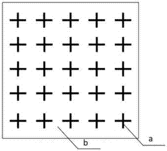
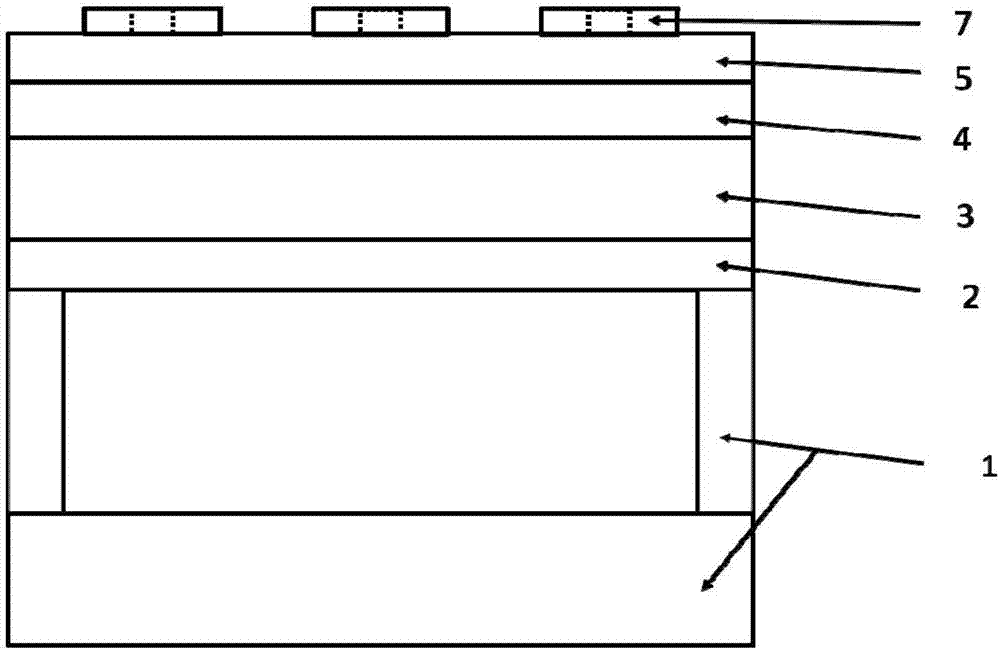
[0051] A lithium tantalate narrow-band detector based on a metasurface, each structural unit includes a silicon base and a support 1, a lower gold electrode 2, a lithium tantalate wafer 3, an upper electrode 4, a dielectric silicon 5, a cross Gold Antenna 7, such as figure 1 shown. Among them, the rod length of the cross gold antenna is 350nm, the rod width is 100nm, and the thickness of the cross gold antenna is 50nm; the unit structure period is 600nm; the thickness of the intermediate silicon layer is 50nm; the thickness of the gold backplane is 100nm. Through numerical simulation, the absorption spectrum of the structure in the infrared band is obtained, by Figure 5 It can be seen that the absorption peak wavelength of this structure is located at 3.24 microns.

Embodiment 2

[0053] A lithium tantalate narrow-band detector based on a metasurface, each structural unit includes a silicon base and a support 1, a lower gold electrode 2, a lithium tantalate wafer 3, an upper electrode 4, a dielectric silicon 5, a cross Gold Antenna 7, such as figure 1 shown. Among them, the rod length of the cross gold antenna is 500nm, the rod width is 100nm, and the thickness of the cross gold antenna is 50nm; the unit structure period is 700nm; the thickness of the intermediate silicon layer is 100nm; the thickness of the gold backplane is 100nm. Through numerical simulation, the absorption spectrum of the structure in the infrared band is obtained, by Figure 6 It can be seen that the absorption peak wavelength of this structure is located at 4.18 microns.

Embodiment 3

[0055] A lithium tantalate narrow-band detector based on a metasurface, each structural unit includes a silicon base and a support 1, a lower gold electrode 2, a lithium tantalate wafer 3, an upper electrode 4, a dielectric silicon 5, a cross Gold Antenna 7, such as figure 1 shown. Among them, the rod length of the cross gold antenna is 750nm, the rod width is 100nm, and the thickness of the cross gold antenna is 50nm; the unit structure period is 1200nm; the thickness of the intermediate silicon layer is 200nm; the thickness of the gold backplane is 100nm. Through numerical simulation, the absorption spectrum of the structure in the infrared band is obtained, by Figure 7 It can be seen that the absorption peak wavelength of this structure is located at 5.8 microns.


PUM

PropertyMeasurementUnit
Thicknessaaaaaaaaaa
Thicknessaaaaaaaaaa
Thicknessaaaaaaaaaa

Abstract

The invention discloses a lithium tantalate narrowband detector and a preparation method thereof, and belongs to the field of pyroelectric infrared detectors. The detector comprises a detector body and an electromagnetic ultra-surface structure, wherein the electromagnetic ultra-surface structure is arranged on the detector body, the detector body comprises from bottom to top, a silicon pedestal support, a lower electrode, a lithium tantalate wafer and an upper electrode, and the electromagnetic ultra-surface structure comprises, from bottom to top, a gold backboard, a dielectric layer and an antenna. The gold backboard and the upper electrode are the same one article. The invention further provides a method for preparing the lithium tantalate narrowband detector. Ultra-surface technology is employed to overcome the defects of lack of wavelength selectivity wavelength selectivity in a conventional pyroelectric detector, detection of specific wavelength in a certain wavelength scope can be realized, and the preparation flow of an infrared detector is simplified.

Description

technical field [0001] The invention belongs to the field of pyroelectric infrared detectors, and relates to a lithium tantalate narrow-band detector based on a metasurface structure and a preparation method. Background technique [0002] Thermal infrared detection and sensing is a key technology with wide application. Compared with expensive photoelectric detection systems working at low temperature, thermal infrared detectors have lower cost and simpler process flow, but because thermal detectors can only respond to heat, they do not have wavelength selectivity and cannot detect specific With a single wavelength, the sensitivity is poorer than that of photodetectors, which to some extent limits the use of thermal infrared detectors in a wider range of fields. [0003] In recent years, as a new electromagnetic material, metasurfaces have become a research hotspot. The electromagnetic properties of metasurfaces are basically independent of the properties of their component...

Claims


Application Information

Patent Timeline
IPC IPC(8): G01J5/20G01J3/42G01J9/00
Inventor 易飞谈小超李君宇甘如雷陈宇瑶郭颂杨奥蒋顺
Owner HUAZHONG UNIV OF SCI & TECH
Why Eureka
Try Eureka