
Intelligent clamping device and active control method therefor

A clamping device and active control technology, applied in the direction of workpiece clamping device, general control system, control/adjustment system, etc., can solve the problems of object damage, inability to consider the uncertainty of the geometric shape of the clamped object, poor applicability, etc.

Inactive Publication Date: 2017-12-15
NORTHWESTERN POLYTECHNICAL UNIV
View PDF6 Cites 0 Cited by
  • Summary
  • Abstract
  • Description
  • Claims
  • Application Information

AI Technical Summary

Problems solved by technology

[0002] Existing clamping devices generally adopt mechanical connection, the rigidity of the clamping claws is fixed, and the clamping force and the deformation of the clamping point are in a linear relationship, which cannot realize the gentle application of the clamping force, especially when clamping brittle objects. cause damage to objects
Moreover, the existing clamping devices are usually designed for the clamped object of a specific size, which cannot take into account the uncertainty of the geometric shape of the clamped object, and the applicability is poor

Method used


Image

  • Intelligent clamping device and active control method therefor
  • Intelligent clamping device and active control method therefor
  • Intelligent clamping device and active control method therefor

Examples


example 1

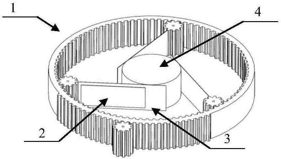
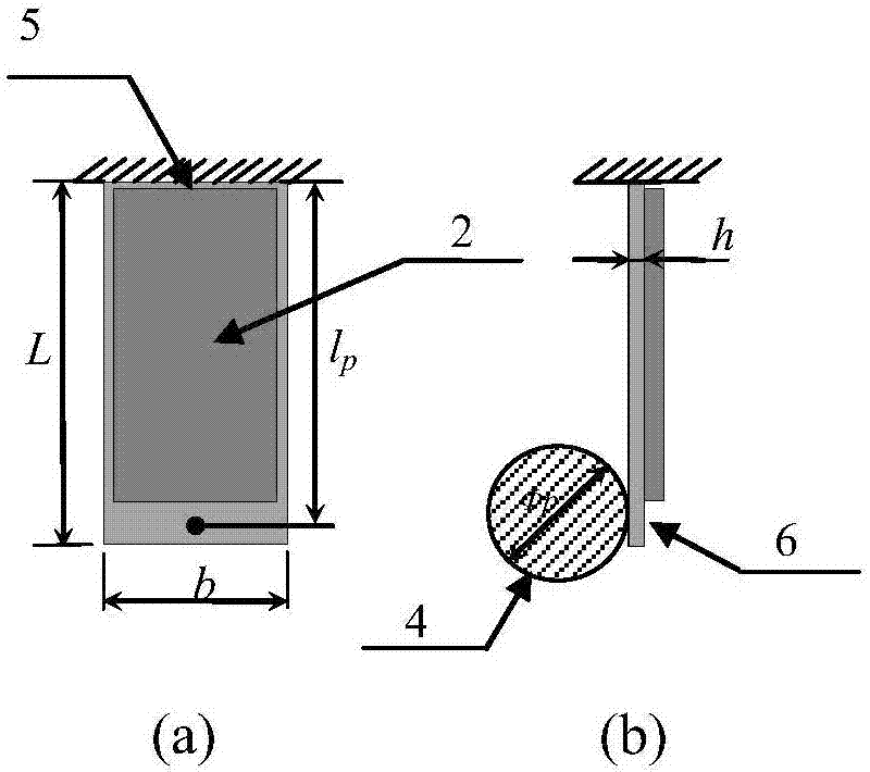
[0059] A cantilever beam model with a length, width and height of 80mm, 40mm and 0.43mm, respectively, pasted with MFC is used to represent the clamping claw in the present invention. The material density of the beam is 8110kg / m 3 , Young's modulus is 200GPa, Poisson's ratio is 0.3. The d33-type (M-5628-P1) MFC piezoelectric film (Smart Material Corp. http: / / www.smart-material.com / MFC-product-main.html) is used, and its maximum and minimum operating voltages are respectively +1500V and -500V. The contact point between the object to be clamped and the clamping jaw (namely point p) is located at 5mm from the end of the cantilever beam, and a mass block is used to simulate the contact load.

[0060] The experimental block diagram is as Figure 6 As shown, Simulink software is used to control the dSPACE semi-physical real-time control simulation system, and the KEYENCE LK-G150 sensor is used to measure the deformation, and the control signal is supplied to the MFC piezoelectric...

example 2

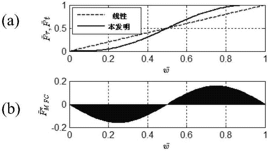
[0067] Example 2 is realized by simulation, and when a single clamping claw exerts a clamping force on the clamped object, the change of the acceleration of the contact point of the clamping claw reflects the change of the clamping force. Taking the experimental model in Example 1 as the object, assuming that the outer rotating ring rotates at an angular velocity ω, the deformation at point p changes linearly from 0 to w within 2s g , using the parameters obtained by the finite element method in Table 1 for numerical simulation verification. In order to illustrate the gentle clamping effect of the present invention, it is compared with the acceleration response of the point p (ie the acceleration during the process of clamping the clamped object) of the clamping jaw with fixed clamping stiffness (ie linear case) in this process. The result of feedforward control is as Figure 8 As shown, it can be seen that the acceleration response in the case of linear clamping stiffness is...


PUM


Abstract

The invention proposes an intelligent clamping device and an active control method therefor. The rigidness of a clamping jaw of the intelligent clamping device can be controlled according to the contact deformation, and the designability of the rigidness of the clamping jaw is achieved through a piezoelectric control MFC-beam model. When the device is used for clamping, the device can intelligently adjust the size of a clamping force, and achieves the slow clamping of a clamped object. The device can flexibly designs the change curve of the clamping force according to the actual demands. The device also can design the diameter of an outer rotating ring and the length of an inner clamping jaw according to the size of the clamped object, and achieves the slow clamping of clamped objects at different sizes.

Description

technical field [0001] The invention belongs to the field of electromechanical engineering and relates to the principle of structural mechanics and the principle of automatic control. Background technique [0002] Existing clamping devices generally adopt mechanical connection, the rigidity of the clamping claws is fixed, and the clamping force and the deformation of the clamping point are in a linear relationship, which cannot realize the gentle application of the clamping force, especially when clamping brittle objects. cause damage to the object. Moreover, the existing clamping devices are usually designed for clamped objects of a specific size, which cannot take into account the uncertainty of the geometric shape of the clamped object, and have poor applicability. Contents of the invention [0003] In order to solve the above two types of technical problems, the present invention proposes an intelligent clamping device and its active control method, which can achieve ...

Claims


Application Information

Patent Timeline
Patent Type & Authority Applications(China)
IPC IPC(8): G05B17/02B25B11/00
CPCB25B11/00G05B17/02
Inventor 穆罕默德·卡西姆杨智春谷迎松贺顺
Owner NORTHWESTERN POLYTECHNICAL UNIV
Learn More