Detecting method of rotor position and rotating speed of permanent magnet synchronous motor

A permanent magnet synchronous motor, rotor position technology, applied in the control of generator, motor control, motor generator control and other directions, can solve the problems of weakening buffeting, influence of estimation accuracy, inaccurate estimation of rotor position and rotational speed, etc. Sliding Mode Buffeting, Complexity Reduction, Effects of Complexity Reduction

Inactive Publication Date: 2017-12-15
CHONGQING UNIV
View PDF5 Cites 21 Cited by
  • Summary
  • Abstract
  • Description
  • Claims
  • Application Information

AI Technical Summary

Problems solved by technology

[0003] The traditional first-order sliding mode observer exhibits inherent chattering phenomenon near the sliding mode surface under the action of the switching function, which makes the estimation result oscillate above and below the actual value, which has a direct impact on the estimation accuracy
Low-pass filters are widely used in first-order sliding-mode observers to filter out high-frequency noise caused by sliding-mode chattering, however, low-pass filters will bring gain attenuation and phase delay, while increasing the complexity of the system
In order to effectively weaken chattering and avoid the use of low-pass filters, the sliding mode control method based on quasi-sliding mode is usually used, that is, the saturation function is used instead of the switching function, and the normal sliding film control is adopted outside the boundary layer. The biggest defect of this method is that the observation error cannot be guaranteed to converge to zero in the boundary layer, which leads to inaccurate estimation of rotor position and speed.

Method used


Image

  • Detecting method of rotor position and rotating speed of permanent magnet synchronous motor
  • Detecting method of rotor position and rotating speed of permanent magnet synchronous motor
  • Detecting method of rotor position and rotating speed of permanent magnet synchronous motor

Examples


Embodiment Construction

[0069] The preferred embodiments of the present invention will be described in detail below with reference to the accompanying drawings.

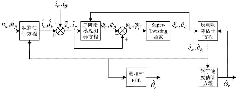
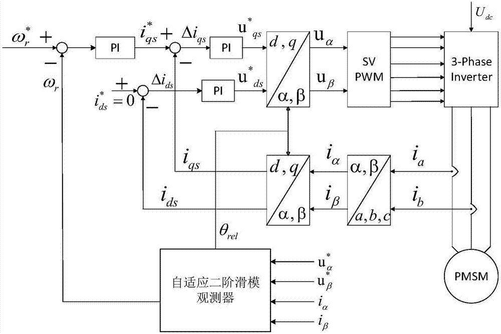
[0070] Such as Figure 1-2 As shown, the present invention firstly relates to the second-order sliding mode control theory based on Super-Twisting Algorithm (STA).

[0071] The simplest form of STA can be written as:

[0072]

[0073] Among them: xi represents the state variable, Indicates the estimated value of the state variable, k i is the switching gain, ρ i Indicates the disturbance term, i=1,2. If its disturbance term is globally bounded, ie ρ 2 = 0, and gain k 1 、k 2 Satisfy

[0074]

[0075] Then the system will converge to the sliding surface in finite time, where δ is any normal constant.

[0076] In the static two-phase α-β coordinate system, the built-in permanent magnet synchronous motor (for the surface-mounted permanent magnet synchronous motor, L q = L d ) The state equation based on the effective flux li...


PUM


Abstract

The invention relates to a detecting method of the rotor position and rotating speed of a permanent magnet synchronous motor, and belongs to the field of permanent magnet synchronous motor control. The detecting method includes the following steps that a counter electromotive force equation and a state equation of the permanent magnet synchronous motor are set up; matrix-vector arrangement is carried out on the state equation set up, and a state estimating equation is set up according to the state equation obtained after arrangement to obtain a state error equation; a second-order sliding-mode observer equation is set up according to the state error equation to obtain a counter electromotive force error equation; the sigmoid function is used for replacing the control function signum to correct the counter electromotive force error equation; a counter electromotive force estimating equation is set up according to the counter electromotive force error equation obtained after correction; the counter electromotive force estimating equation is subtracted from the counter electromotive force equation, the Lyapunov equation is used for analyzing stability to obtain and correct a rotor rotating speed estimating equation; rotor position information is extracted through the phase-locked loop technology. A model reference adaption and second-order sliding-mode combined observer is used for estimating counter electromotive force and rotor speed of the permanent magnet synchronous motor and replacing a traditional sliding-mode observer to obtain the rotor speed through counter electromotive force numerical calculation.

Description

technical field [0001] The invention belongs to the field of permanent magnet synchronous motor control, and relates to a method for detecting the rotor position and rotational speed of a permanent magnet synchronous motor. Background technique [0002] At present, in the middle and high speed segments, the rotor position and speed detection methods of the sensorless vector control system of permanent magnet synchronous motors mainly include model reference adaptive method, extended Kalman filter method and sliding mode observer method. The model reference adaptive method takes the mathematical model of the permanent magnet synchronous motor as the reference model, and uses the equation containing the parameters to be estimated as the adjustable model. The two models have the same physical meaning of the output. Appropriate adaptive law to realize the detection of the rotor position and speed of permanent magnet synchronous motors depends heavily on the accuracy of motor par...

Claims


Application Information

Patent Timeline
Patent Type & Authority Applications(China)
IPC IPC(8): H02P21/13H02P21/18H02P21/26H02P25/026H02P27/08
CPCH02P21/0007H02P21/13H02P21/18H02P21/26H02P25/03H02P27/08H02P2203/03H02P2203/09
Inventor 张谦李东
Owner CHONGQING UNIV
Why Eureka
Try Eureka