Electronic warehouse of an automatic vertical drilling tool

A technology of vertical drilling and electronic warehouse, applied in the field of electronic warehouse, which can solve the problems of tools not working properly, difficult disassembly and assembly of electronic warehouse, damage to electronic components, etc., to achieve the effect of convenient disassembly and assembly, simple structure and ensuring safety

Active Publication Date: 2019-01-22
BAOJI PETROLEUM MASCH CO LTD +2
View PDF5 Cites 0 Cited by
  • Summary
  • Abstract
  • Description
  • Claims
  • Application Information

AI Technical Summary

Problems solved by technology

[0004] The purpose of the present invention is to provide an electronic warehouse of an automatic vertical drilling tool, which solves the problems in the prior art that the electronic warehouse enters liquid, the electronic components heat up, and the electronic components are damaged, which leads to the tool not working normally; at the same time, it solves the problem of Storage of a large amount of operation data, control program downhole small closed-loop control, solenoid valve stuck when the control command controls the solenoid valve, fast self-inspection of electrical components in the electronic warehouse, fast reading and playback of stored operation data, and difficult disassembly and assembly of the electronic warehouse

Method used


Image

  • Electronic warehouse of an automatic vertical drilling tool
  • Electronic warehouse of an automatic vertical drilling tool
  • Electronic warehouse of an automatic vertical drilling tool

Examples


Embodiment Construction

[0023] The present invention will be described in detail below in conjunction with the accompanying drawings and specific embodiments.

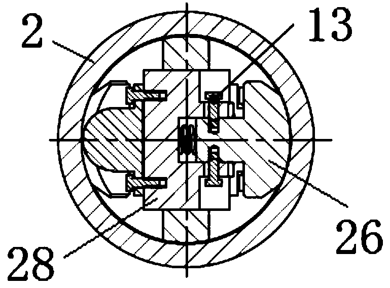
[0024] Numbers in parentheses in the drawings indicate components of the same structure installed at different locations.

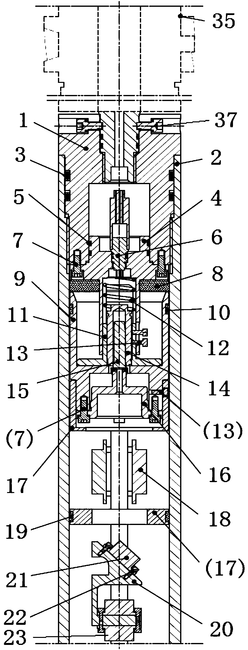
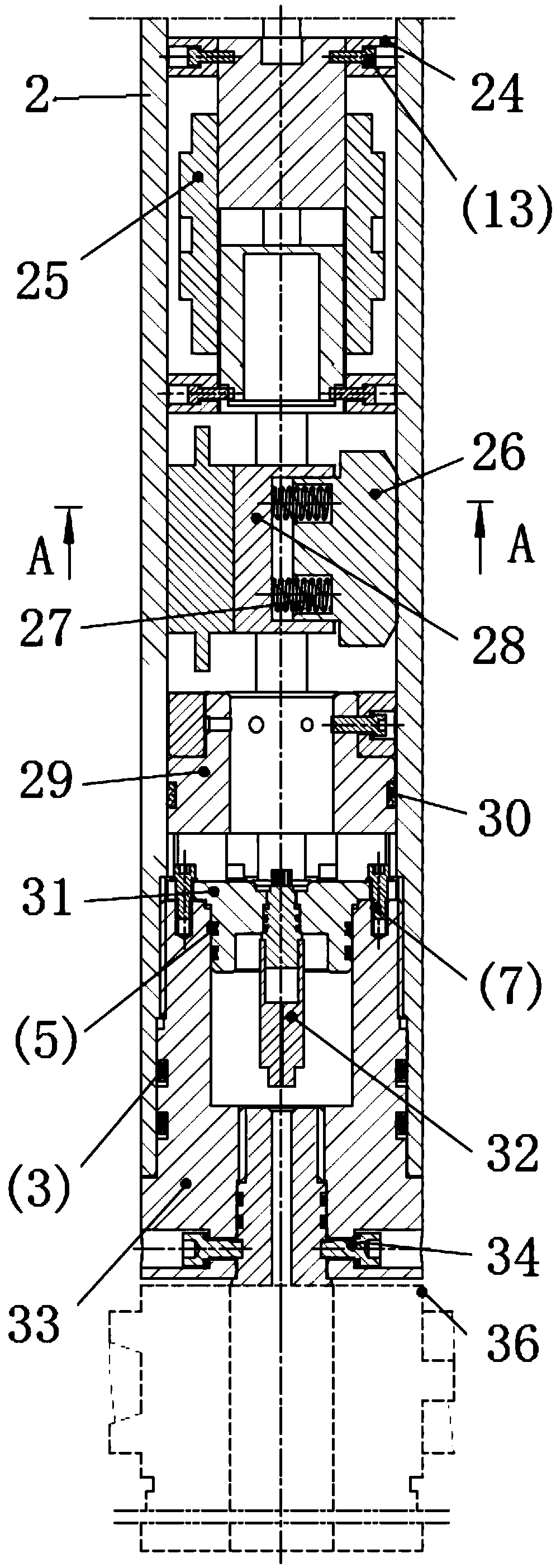
[0025] refer to figure 1 , figure 2 The structure of the present invention is to include the electronic warehouse outer cylinder 2, in which the electronic warehouse outer cylinder 2 is sequentially provided with a slip ring structure, a measurement and control storage structure, a heat dissipation structure and an electronic warehouse sealing transmission structure,

[0026] The slip ring structure is that the upper end of the outer cylinder 2 of the electronic warehouse is fastened with the upper plug 1, and the outer diameter hole of the upper plug 1 is equipped with a limit screw 37, and the inner end of the limit screw 37 is connected with the transmission shaft of the upper turbine generator 35. Top connection; ...


PUM


Abstract

The invention discloses an electronic storehouse of an automatic vertical drilling tool. A sliding ring structure, a monitoring and controlling storage structure, a heat dissipating structure and an electronic storehouse sealing transmission structure are arranged in an outer barrel of the electronic storehouse. According to the sliding ring structure, an upper plug cap limiting screw is connected with the top of an upper turbine generator transmission shaft; the lower end surface of the upper plug cap is connected with an upper main bracket; the upper main bracket is in pressed contact with a sliding ring bracket sleeve through a damping pad, a sliding ring guiding sleeve in an inner hole of the sliding ring bracket sleeve is connected with the lower end of the upper main bracket, and the lower end of a sliding ring spring of an inner hole of the upper main bracket is in pressed contact with the upper end of a sliding ring fast connecting ring; the outer diameter of the sliding ring fast connecting ring is in buckled connection with the sliding ring guiding sleeve; an inner hole of the sliding ring fast connecting ring is downwards connected with the sliding ring bracket sleeve through an air quick connector and a inserting part fixing frame, and the sliding ring bracket sleeve is fixedly connected with a main skeleton. According to the electronic storehouse sealing transmission structure, a skeleton joint is fixedly connected with the main skeleton, and the main skeleton is downwards fixed to a lower main bracket and a lower plug cap. According to the electronic storehouse of the automatic vertical drilling tool, fast self-detecting is achieved, and disassembly and assembly are convenient.

Description

technical field [0001] The invention belongs to the technical field of mechanical equipment, and relates to an electronic warehouse of an automatic vertical drilling tool. Background technique [0002] The automatic vertical drilling tool is a drilling tool system that integrates machinery, electricity and hydraulics to independently correct and stabilize the deviation, and can effectively solve the problems of preventing deviation and driving fast, which plague the drilling engineering field. "An automatic vertical drilling tool (invention patent number ZL201410612485.X)" is a drilling system based on the principle of automatic control, autonomous guidance, high reliability, long life and high sensitivity, designed for the needs of vertical drilling technology of oil wells. The main function of this tool is to ensure that the maximum inclination angle of the drilled vertical section does not exceed 1.0° without reducing the normal drilling pressure through the autonomous gu...

Claims


Application Information

Patent Timeline
Patent Type & Authority Patents(China)
IPC IPC(8): E21B7/04E21B7/10E21B44/00E21B47/022F03B13/00
CPCE21B7/04E21B7/10E21B44/00E21B47/022F03B13/00
Inventor 王闻涛杨晓勇田凤仙李唐都卞志楠
Owner BAOJI PETROLEUM MASCH CO LTD
Why Eureka
Try Eureka