Material drying mechanical equipment

A technology for mechanical equipment and materials, applied in the field of drying machinery and equipment for materials, can solve problems such as energy loss, low degree of mechanization, and inability to easily adjust drying temperature, so as to reduce heat loss, avoid a large amount of heat loss, and save energy. energy effect

Inactive Publication Date: 2017-12-22
HUANGHUAI UNIV
View PDF5 Cites 9 Cited by
  • Summary
  • Abstract
  • Description
  • Claims
  • Application Information

AI Technical Summary

Problems solved by technology

[0002] Drying machinery and equipment have several modes such as belt drying, drum drying, box drying, tower drying, etc.; heat sources include coal, electricity, gas, etc.; materials have heat radiation during the drying process, etc., heat energy Radiant drying means that the heat flow is in full contact with the material, and the heat is fully utilized through heat conduction, convection, and radiation transfer; the heat energy is directly transferred to the material, so that the moisture in the material is continuously evaporated, and the drying of the material is realized. However, the current drying Mechanical equipment has the problems of serious energy loss, low degree of mechanization, inability to conveniently adjust the required drying temperature and inability to provide a more uniform drying temperature environment

Method used


Image

  • Material drying mechanical equipment
  • Material drying mechanical equipment
  • Material drying mechanical equipment

Examples


Embodiment Construction

[0019] The following will clearly and completely describe the technical solutions in the embodiments of the present invention with reference to the accompanying drawings in the embodiments of the present invention. Obviously, the described embodiments are only some, not all, embodiments of the present invention. Based on the embodiments of the present invention, all other embodiments obtained by persons of ordinary skill in the art without making creative efforts belong to the protection scope of the present invention.

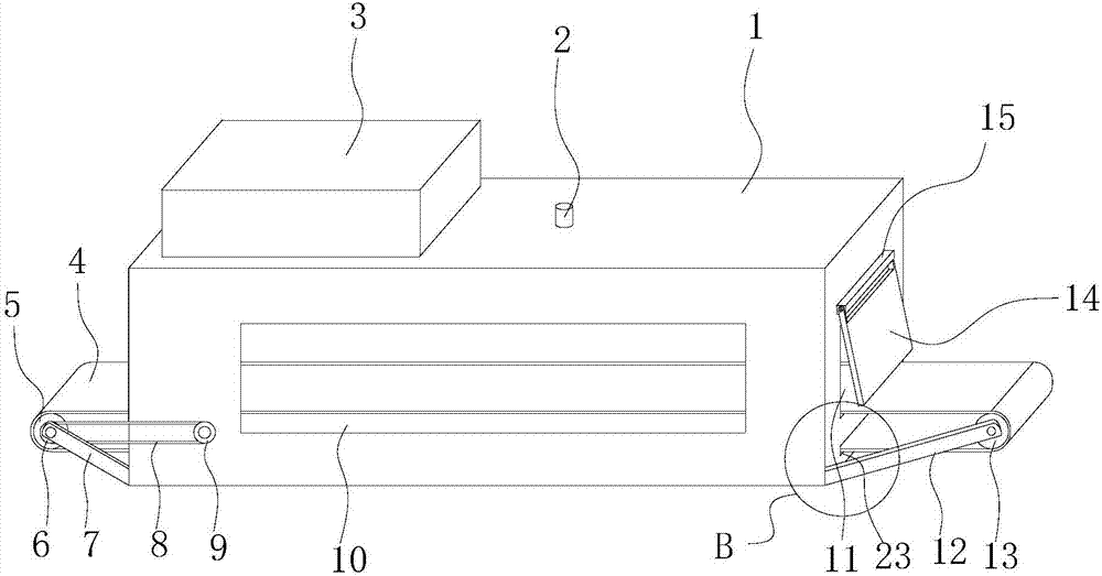
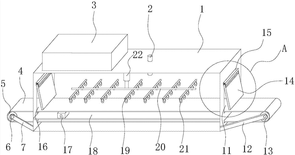
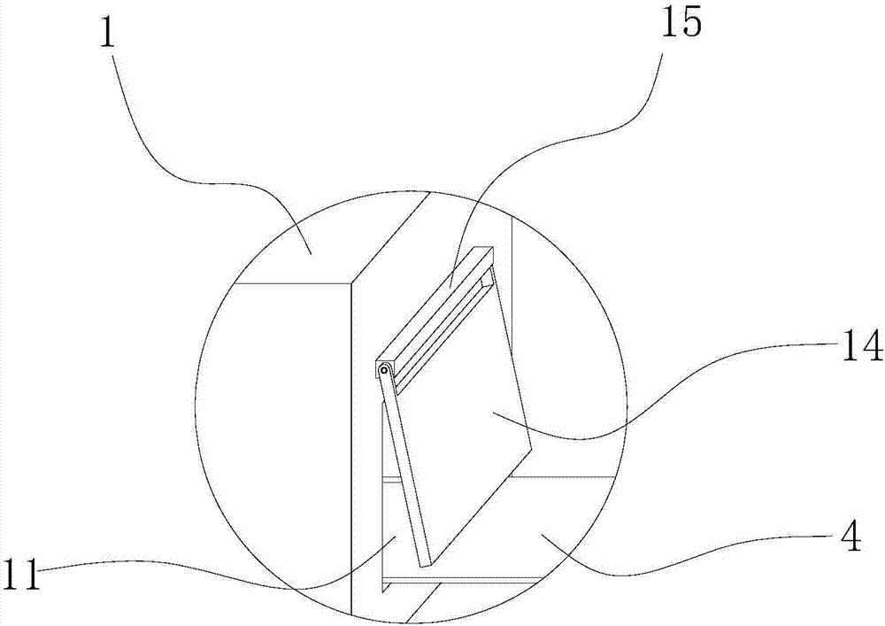
[0020] see Figure 1-5 , the invention provides a technical solution: a kind of material drying mechanical equipment, including a drying box 1, a feed port 16 is opened on the side wall of one end of the drying box 1, and the other end side of the drying box 1 The wall is provided with a discharge port 11, and the inner wall of the feed port 16 and the outer wall of the discharge port 11 are respectively welded with limit fixing columns 15 arranged in the hori...


PUM


Abstract

The invention discloses material drying mechanical equipment which comprises a drying box provided with a feeding inlet and a discharging outlet. Limiting fixing columns are welded to the inner wall of the feeding inlet and the outer wall of the discharging outlet, and baffles are hinged to the limiting fixing columns. The drying box is correspondingly provided with a driving carrier roller and a driven carrier roller through a first rotating shaft support and a second rotating shaft support, an electric push rod is fixed to the inner top face of the drying box, a first telescopic rod is fixed to the end of a telescopic rod of the electric push rod, a second supporting rod is fixed to the first supporting rod, and an infrared heating lamp is fixed to the second supporting rod. A temperature sensor is fixed to the upper surface of the drying box, an electrical box is arranged at one end of the upper surface of the drying box, and the electrical box is internally provided with a constant-temperature controller, a power-on and power-off controller and a PLC. According to the material drying mechanical equipment, energy is saved, the mechanization degree is high, the drying temperature can be conveniently adjusted, and a uniform drying temperature environment can be provided.

Description

technical field [0001] The invention relates to the technical field of drying machinery and equipment, in particular to a material drying machinery and equipment. Background technique [0002] Drying machinery and equipment have several modes such as belt drying, drum drying, box drying, tower drying, etc.; heat sources include coal, electricity, gas, etc.; materials have heat radiation during the drying process, etc., heat energy Radiant drying means that the heat flow is in full contact with the material, and the heat is fully utilized through heat conduction, convection, and radiation transfer; the heat energy is directly transferred to the material, so that the moisture in the material is continuously evaporated, and the drying of the material is realized. However, the current drying Mechanical equipment has the problems of serious energy loss, low degree of mechanization, inability to conveniently adjust the required drying temperature and inability to provide a relativ...

Claims


Application Information

Patent Timeline
Patent Type & Authority Applications(China)
IPC IPC(8): F26B15/18F26B3/30F26B23/04F26B25/02F26B25/00F26B25/12
CPCF26B3/30F26B15/18F26B23/04F26B25/00F26B25/008F26B25/02F26B25/12
Inventor 肖伟中张艳山高迎春
Owner HUANGHUAI UNIV
Why Eureka
Try Eureka