Wing heat tube type radiator structure for engineering vehicle

An engineering vehicle, heat pipe technology, applied in indirect heat exchangers, heat transfer modification, heat exchange equipment, etc., can solve the problem that the heat dissipation effect is difficult to meet the system requirements.

Inactive Publication Date: 2017-12-22
NORTH CHINA UNIVERSITY OF SCIENCE AND TECHNOLOGY
View PDF6 Cites 1 Cited by
  • Summary
  • Abstract
  • Description
  • Claims
  • Application Information

AI Technical Summary

Problems solved by technology

[0003] In the current product design, the heat pipes of tube-fin radiators are usually flat tubes. However, with the continuous improvement of vehicle performance, the heat dissipation effect is sometimes difficult to meet the system requirements.

Method used


Image

  • Wing heat tube type radiator structure for engineering vehicle
  • Wing heat tube type radiator structure for engineering vehicle
  • Wing heat tube type radiator structure for engineering vehicle

Examples


Embodiment Construction

[0024] The present invention will be described in detail below in conjunction with the accompanying drawings and embodiments, but the present embodiments do not constitute any limitation to the present invention.

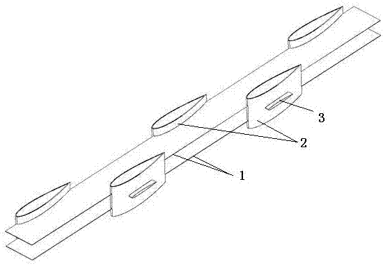
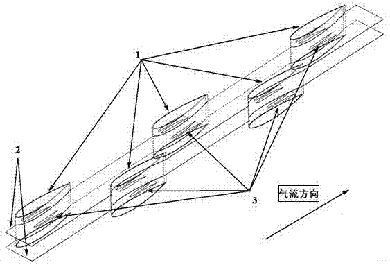
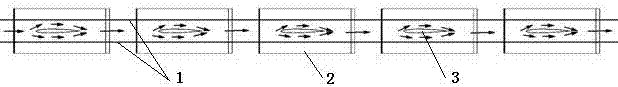
[0025] See attached Figure 1 to Figure 8 , an airfoil heat pipe radiator structure for an engineering vehicle, which is composed of a fin 1, an aircraft airfoil heat pipe 2, and a drainage device 3, the two side walls of the aircraft airfoil heat pipe 2 are equipped with a drainage device 3, and the surface of the drainage device 3 has Similar to the airfoil characteristics of the aircraft airfoil heat pipe 2 , the drainage device 3 is located between the upper and lower layers of fins 1 , and does not contact or connect with the fins 1 . The connection between the drainage device 3 and the aircraft airfoil heat pipe 2 is a fixed structure by brazing; the drainage device 3 can be solid or hollow, and the hollow drainage device 3 is a fully enclosed structure when t...


PUM


Abstract

The invention discloses a wing heat tube type radiator structure for an engineering vehicle. The wing heat tube type radiator structure comprises wings and heat tubes, wherein the heat tubes are in the shape of aircraft wing; drainage devices are arranged on two side walls of each heat tube; outer surfaces of the drainage devices are provided with wing type characteristics similar with those of the aircraft wing type heat tubes or triangular wing plates; and the drainage devices are positioned between upper and lower layers of wings, and are not in contact or connection with the wings. While low-resistance aircraft wing type heat tubes reduce air flowing resistance as much as possible, air which flows into a radiator is drained; the drainage devices are used for guiding air flow and forcing air to flow in a runner, so that the temperature of air near high-temperature solid is reduced, and performances are improved; and mounting angles of the drainage devices are regulated, so that spiral flow (seen in figure 6) under a relatively ideal state is obtained in a mode of controlling air speed direction on the premise of reducing air flowing resistance as much as possible, and therefore, convection heat exchange effect is improved.

Description

technical field [0001] The invention relates to a tube-fin radiator, in particular to an airfoil heat pipe radiator structure for an engineering vehicle that can improve the working performance of the radiator of the engine cooling system in the engine compartment of the engineering vehicle. Background technique [0002] Engineering vehicles usually use a high-power diesel engine as a power source. When the fuel is burned, a large amount of heat is generated. This part of the heat is transferred to the coolant through the cylinder wall. The cold air performs heat exchange, so as to achieve the purpose of cooling and dissipating heat from the engine. Reasonable cylinder temperature is conducive to improving fuel combustion efficiency, thereby ensuring the working stability of the engine and realizing energy saving of the system. The tube-fin radiator has good structural characteristics, heat exchange effect and anti-clogging performance, and is suitable for the common harsh ...

Claims


Application Information

Patent Timeline
Patent Type & Authority Applications(China)
IPC IPC(8): F28D15/02F28F13/06F01P11/00
CPCF28D15/02F01P11/00F28F13/06
Inventor 刘佳鑫王宝中龙海洋张琳婷高玲焕郭媛媛邢梦龙
Owner NORTH CHINA UNIVERSITY OF SCIENCE AND TECHNOLOGY
Why Eureka
Try Eureka