Three-dimensional fiber Bragg grating wind speed and direction sensor and system

An optical fiber Bragg, wind speed and direction technology, applied in signal transmission systems, non-electrical signal transmission systems, instruments, etc., can solve the problems of large sensor measurement error, interference, sensor measurement error, etc., to ensure reliability, good stability, The effect of high measurement accuracy

Active Publication Date: 2017-12-22
HARBIN ENG UNIV +3
View PDF7 Cites 9 Cited by
  • Summary
  • Abstract
  • Description
  • Claims
  • Application Information

AI Technical Summary

Problems solved by technology

However, the current wind speed and direction measurement equipment has certain deficiencies in stability, accuracy, responsiveness, corrosion resistance, anti-electromagnetic interference and remote detection. For example, Li Chengrong and Ma Guoming of North China Electric Power University developed the " Fiber Bragg Grating Wind Speed ​​Sensor and System for Ice Covered Monitoring of Transmission Lines" Application No.: 201010621828.0, Publication No.: CN102175888A, due to the influence of ambient temperature, the measurement error of the sensor is relatively large, and the error value can reach 5pm; published by Wang Chang et al. in 2012 In his paper "Research on All-Fiber Optic Wind Velocity Sensor and Its Sensor Network Applied to Wind Power Generation", the fiber Bragg grating is pasted on the elastic arm that presses the eccentric cam, and the corresponding wind speed is obtained by the change frequency of the fiber Bragg grating wavelength. value, although this method can eliminate the influence of temperature, but the sensor also has measurement errors at low wind speeds

Method used


Image

  • Three-dimensional fiber Bragg grating wind speed and direction sensor and system
  • Three-dimensional fiber Bragg grating wind speed and direction sensor and system
  • Three-dimensional fiber Bragg grating wind speed and direction sensor and system

Examples


Embodiment Construction

[0020] The present invention will be described in further detail below in conjunction with the accompanying drawings and embodiments.

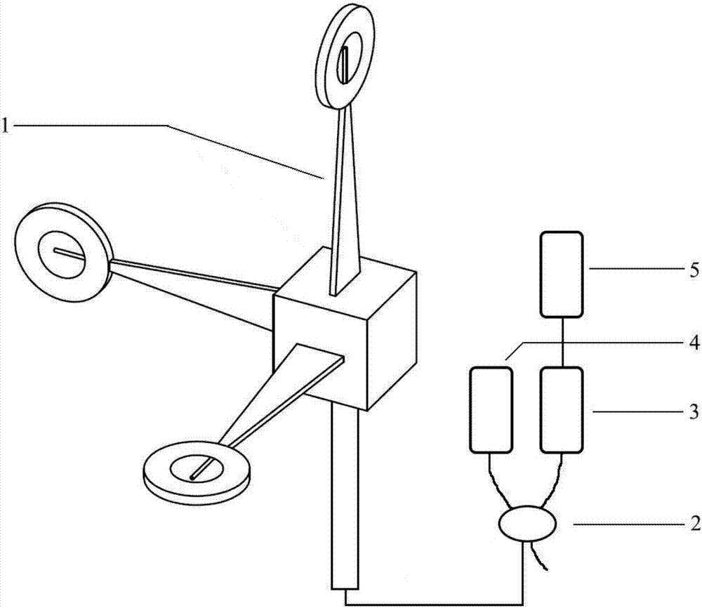
[0021] Such as image 3 As shown, a three-dimensional fiber Bragg grating wind speed and direction sensing system of the present invention includes a three-dimensional fiber Bragg grating wind speed and direction sensor, an optical fiber coupler 2, a wavelength demodulation device 3, a broadband light source 4, and a module computing device 5. The three-dimensional The fiber Bragg grating wind speed and direction sensor is connected to the fiber coupler 2 through optical fiber, and the fiber coupler 2 is respectively connected to the broadband light source 4 and the wavelength demodulation device 3 , and the wavelength demodulation device 3 is connected to the module computing device 5 .

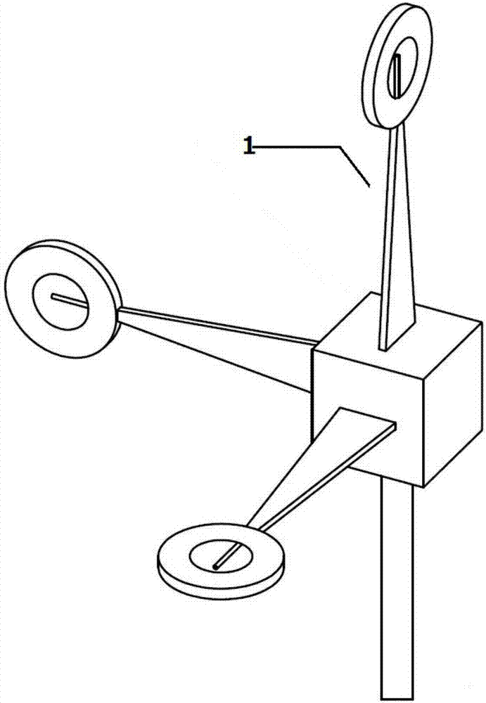
[0022] Such as figure 1 As shown, the three-dimensional fiber Bragg grating wind speed and direction sensor includes a base and three groups of sensing dev...


PUM


Abstract

The present invention relates to a three-dimensional fiber Bragg grating wind speed and direction sensor and system. The sensor comprises a base and three groups of sensing devices mounted on the base. The three groups of sensing devices are arranged on the three surfaces of the base according to a space rectangular coordinate system. The system includes a three-dimensional fiber Bragg grating wind speed and direction sensor, a fiber coupler, a wavelength demodulation device, a broadband light source and a module operation device, the three-dimensional fiber Bragg grating wind speed and direction sensor is connected with the fiber coupler through an optical fiber, the fiber coupler is connected to the broadband light source and the wavelength demodulation device, and the wavelength demodulation device and the module operation device are connected. The invention adopts a non-rotating structure and an independent temperature compensating grating. The sensor has the advantages of small volume, simple structure, high measuring precision and good stability. In addition, the sensor can measure the wind speed and the wind direction at the same time, and a plurality of sensors are arranged to form a measuring network, to achieve multi-point measurement. In addition, the sensor achieves seamless access with equipment based on fiber grating technology.

Description

Technical field: [0001] The invention belongs to the technical field of optical fiber sensors, and in particular relates to a three-dimensional optical fiber Bragg grating wind speed and wind direction sensor and a system. Background technique: [0002] At present, there are many kinds of sensors for measuring wind speed and direction, such as pitot tube wind speed sensor, hot film wind speed and wind direction sensor, ultrasonic wind speed and wind direction sensor, and traditional mechanical sensor wind speed and wind direction sensor. However, the current wind speed and direction measurement equipment has certain deficiencies in stability, accuracy, responsiveness, corrosion resistance, anti-electromagnetic interference and remote detection. For example, Li Chengrong and Ma Guoming of North China Electric Power University developed the " Fiber Bragg Grating Wind Speed ​​Sensor and System for Ice Covered Monitoring of Transmission Lines" Application No.: 201010621828.0, Pu...

Claims


Application Information

Patent Timeline
Patent Type & Authority Applications(China)
IPC IPC(8): G01P5/26G01P13/02G08C23/06
CPCG01P5/26G01P13/025G08C23/06
Inventor 张洪泉姜宗泽杨军张凯刘秀杰
Owner HARBIN ENG UNIV
Why Eureka
Try Eureka