
A Prediction and Compensation Method of Micro Groove Machining Deformation Error

A technology of deformation error and compensation method, applied in metal processing equipment, metal processing mechanical parts, manufacturing tools, etc., can solve the problems affecting the quality of micro groove processing, errors, and inability to real-time error correction.

Active Publication Date: 2019-04-05
BEIJING INSTITUTE OF TECHNOLOGYGY
View PDF6 Cites 0 Cited by
  • Summary
  • Abstract
  • Description
  • Claims
  • Application Information

AI Technical Summary

Problems solved by technology

By obtaining the quantified value and then correcting the tool path and tool trajectory of the programmed program, and then processing the micro-groove, but this method is equivalent to the grooving process in the static process, and the error correction of the micro-groove processing cannot be performed in real time, and there are many problems. The hysteresis, which leads to the gradual accumulation of errors that are not fully controlled in the processing process, and finally a relatively large error, which affects the processing quality of micro grooves

Method used


Image

  • A Prediction and Compensation Method of Micro Groove Machining Deformation Error
  • A Prediction and Compensation Method of Micro Groove Machining Deformation Error
  • A Prediction and Compensation Method of Micro Groove Machining Deformation Error

Examples


Embodiment Construction

[0073] The present invention will be described in detail below in conjunction with the accompanying drawings and specific examples.

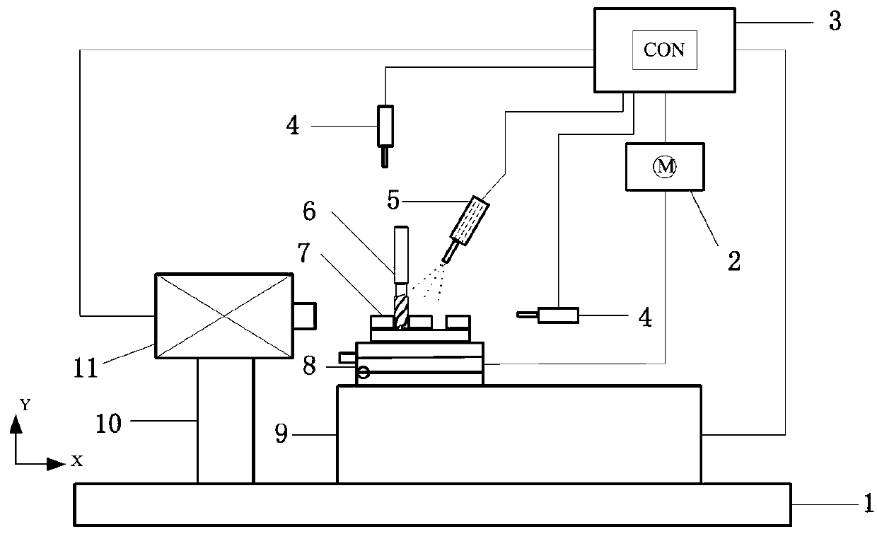
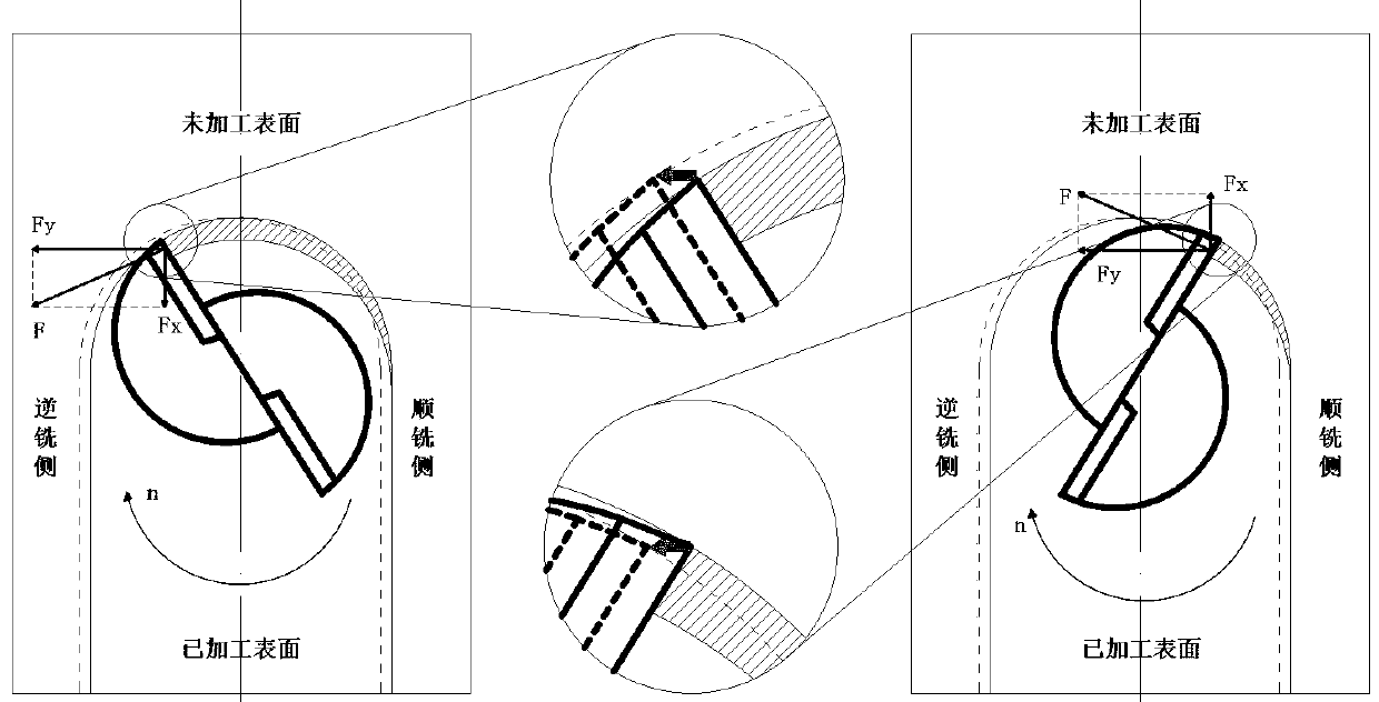
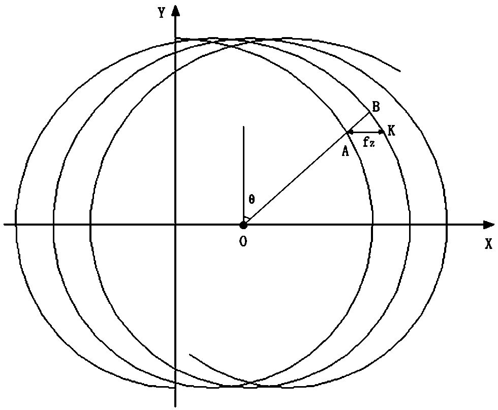
[0074] The present invention is aimed at micromachining (mesoscopic scale) which requires higher processing quality and compensation, and both the scale of the workpiece and the scale of the required features are relatively small. By building a micro-groove processing system, calibrate the cutting force and each cutting force coefficient and compare it with the measured micro-cutting force, and use the theoretical model of the micro-groove as a reference standard to calculate the total deformation value during the micro-grooving process in real time. The total deformation value obtained by real-time measurement and calculation is used to adjust the processing parameters and offset, so as to complete the online deformation prediction and compensation requirements of micro groove workpiece processing.

[0075] Such as figure 1 , 2 , 3, 4, 5, 6, ...


PUM


Abstract

The invention relates to the field of mechanical processing, specifically a method for predicting and compensating machining deformation errors. The invention includes a machine tool table, a micro-milling cutter, a micro-groove piece, a dynamometer and a bracket, and the dynamometer and the bracket are arranged in parallel On the machine tool workbench, the invention utilizes the displacement sensor to monitor the processing deformation of the micro-groove parts online in real time, and uses the sensor workbench to transmit the adjustment information to adjust the micro-groove parts in real time, eliminating the radial undershoot caused by the deformation of the workpiece. Eliminate uncertain factors caused by human adjustment, improve machining accuracy and workpiece quality; the adjuster of the present invention is independent of the machine tool control system, and will not affect the tool path planned by the existing program, which greatly saves programming time and improves Productivity.

Description

technical field [0001] The invention relates to the field of machining, in particular to a method for predicting and compensating machining deformation errors. Background technique [0002] Micro-groove parts are widely used in various fields, such as aerospace, medical equipment, biomedicine, communication information and fuel cells and other micro-machines. The structure of micro-machines is complex and requires high precision in shape and position. Micro-slots are an important part of micro-machines, and it is of great significance to ensure their machining accuracy. The deformation caused by force, heat, stiffness change, flutter and eccentricity during processing is the main cause of machining errors in micro-groove machining. Usually, this part of the error is reduced by selecting reasonable processing parameters and using cutting fluid. However, this method requires too much experience, and the selection of parameters usually consumes a relatively large amount of tim...

Claims


Application Information

Patent Timeline
Patent Type & Authority Patents(China)
IPC IPC(8): B23C3/28B23Q17/00
CPCB23C3/28B23Q17/00
Inventor 焦黎彭振新王西彬王东前毛海俊史雪春陈仕齐刘志兵
Owner BEIJING INSTITUTE OF TECHNOLOGYGY
Learn More