Continuous flow upright type planar liquid-phase shearing method

A planar, liquid-phase technology, applied in the direction of molybdenum sulfide, graphene, nano-carbon, etc., can solve problems such as large area, high stability requirements of power consumption devices, and inner barrel speed limit

Active Publication Date: 2017-12-29
NANTONG UNIVERSITY
View PDF5 Cites 2 Cited by
  • Summary
  • Abstract
  • Description
  • Claims
  • Application Information

AI Technical Summary

Problems solved by technology

Conventional liquid phase shearing devices are divided into two categories: flat plate type and cylindrical type. The flat type means that the upper and lower plates are arranged in parallel, and the relative motion between the two plates is used to provide a velocity gradient, which is suitable for small batch research in laboratory systems. ;Cylindrical type uses the narrow space between the coaxial cylindrical surfaces, and the inner barrel rotates at high speed to provide a velocity gra

Method used


Image

  • Continuous flow upright type planar liquid-phase shearing method
  • Continuous flow upright type planar liquid-phase shearing method
  • Continuous flow upright type planar liquid-phase shearing method

Examples


Embodiment Construction

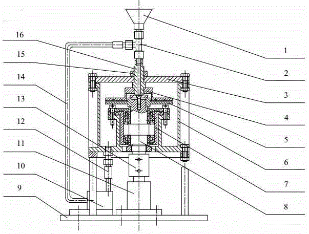
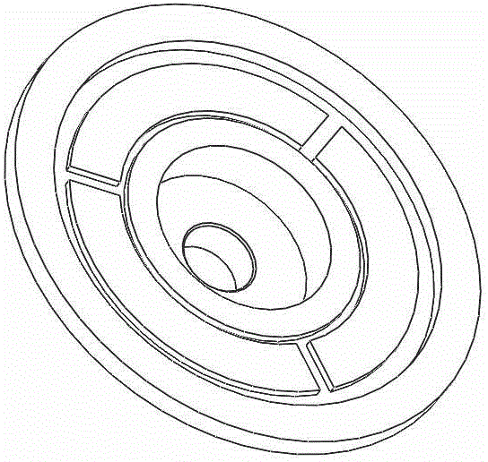
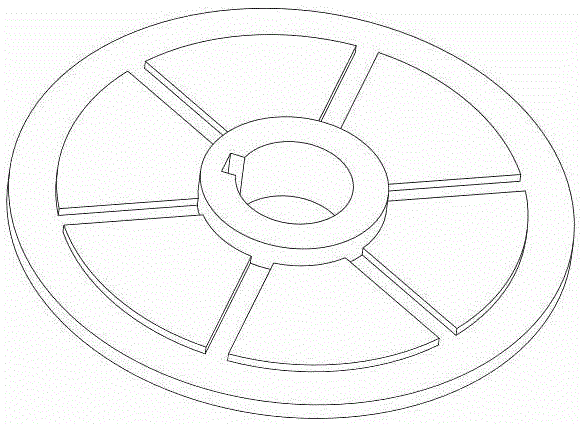
[0017] A continuous flow vertical planar liquid phase shearing method, using a continuous flow vertical planar liquid phase shearing device; the layered precursor material to be processed is mixed in the liquid, injected into the device from the feed port, and passed through the tee joint And the upper shaft enters between the upper plate and the lower plate; there is a certain gap between the upper and lower plates, and the intermittent amount can be adjusted by the thread between the upper cover plate and the upper shaft; there is relative movement between the upper and lower plates during work, and the upper plate The disc is fixed on the upper shaft and remains still during work. The lower disc and the lower shaft are connected by keys, and the lower shaft is driven by a vertical motor. When the lower disc rotates, the fluid between the two will generate laminar flow and turbulent flow at the same time. Due to the high-speed liquid phase shear force provided by the velocity...


PUM


Abstract

The invention discloses a continuous flow upright type planar liquid-phase shearing method which comprises the following steps: mixing a processed laminar precursor material with a liquid, injecting into a device from a feeding hole, and feeding into a part between an upper disc and a lower disc; when the lower disc is rotated, enabling the fluid between the upper disc and the lower disc to flow in a laminar manner and a turbulent manner simultaneously; and feeding a liquid material into a liquid cavity after one round of liquid-phase shearing processing, feeding back to the part between the upper disc and the lower disc by using a hydraulic pump through a tube connector, a backflow tube and a three-way tube connector, performing liquid-phase shearing processing for another time, and circulating the liquid for multiple times till processing requirements are met completely. The method is excellent in working property.

Description

technical field [0001] The invention relates to a liquid phase shearing device. Background technique [0002] Since the new century, graphene (Graphene) and molybdenum disulfide (MoS 2 ) has been a research hotspot all over the world, and their unique physical properties have been discovered one after another, such as the ultrafast electron transport and heat transport capabilities of graphene, single-layer or few-layer MoS 2 The optical response and radiation resistance properties caused by the unique energy level structure, etc., as far as the laboratory level is concerned, various new materials based on them have shown potential advantages in the fields of catalysis, energy and sensors, and have become the world's The key direction of each country's competing development. However, as far as the preparation of two-dimensional materials is concerned, their preparation has also gone through a relatively complicated process. Starting from the initial micromechanical exfolia...

Claims


Application Information

Patent Timeline
IPC IPC(8): C01B32/19C01G39/06
CPCC01G39/06
Inventor 袁国秋莫亚梅曹敏张兴国姚理荣
Owner NANTONG UNIVERSITY
Why Eureka
Try Eureka