Construction site drainage method using water collecting well

A technology for construction sites and water collection wells, applied in water conservancy projects, drainage structures, artificial islands, etc., can solve problems such as unfavorable construction site standardization management and civilized construction requirements, unfavorable construction cost savings, and inability to reuse, etc. Drainage problems, ensuring smooth drainage, and the effect of simple structure

Inactive Publication Date: 2017-12-29
MCC5 GROUP CORP SHANGHAI
View PDF10 Cites 1 Cited by
  • Summary
  • Abstract
  • Description
  • Claims
  • Application Information

AI Technical Summary

Problems solved by technology

The general drainage method basically adopts open-cut drainage ditches and water collection wells, brick drainage ditches and water collection wells, etc.: Although the open-cut method is simple and economical, it is full of dirt ditches and is easy to be blocked, which is not conducive to standardized management of the construction site and civilized construction Requirements: Although the brickwork method is conducive to standardized management, it is basically a one-time cost input and use, which cannot be reused, is not conducive to saving construction costs, and is not economical and practical
[0003] Therefore, there are above-mentioned inconveniences and problems in the known construction site drainage method

Method used


Image

  • Construction site drainage method using water collecting well
  • Construction site drainage method using water collecting well
  • Construction site drainage method using water collecting well

Examples


Embodiment 1

[0030] The construction site drainage method using the water collection well of the present invention comprises the following steps:

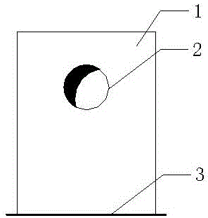
[0031] see now figure 1 , figure 1 It is a schematic diagram of the structure of the water collection well in the embodiment of the present invention.

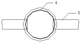
[0032] a. Set up the drainage steel pipe 5 pipeline: use the construction waste steel pipe DN300*4mm as the drainage pipeline, and the joints of the steel pipe pipeline shall be welded.

[0033] b. Make the water collection well: use a large-diameter pipe DN1000*8mm, cut a section of 1.8m long as the wall of the water collection well, and cut a circular steel plate with a diameter 100mm larger than the large-diameter pipe DN1000 and a thickness of 8mm as the bottom plate of the water collection well. Weld the steel plate bottom plate and the steel pipe well wall, and cut a hole with a diameter 5-8mm larger than the outer diameter of the drainage pipe by gas cutting or plasma cutting at 500mm ...


PUM


Abstract

A construction site drainage method using a water collecting well is characterized by comprising the following steps that 1, a drainage steel-pipe (5) pipeline is set; 2, the water collecting well is built; 3, a protection net cover of the water collecting well is prepared; 4, a drainage steel-pipe (5) pipeline trench is dug; 5, the drainage steel-pipe (5) pipeline and the water collecting well are embedded and installed; 6, the protection net cover of the water collecting well is installed; 7, dismantling is conducted for reuse, wherein according to the need of an engineering site, and after the construction project is finished, both the drainage pipeline and the water collecting well can be dug out for recycling and be reused in the next construction project. The construction site drainage method using the water collecting well has the advantages that the water collecting well is simple in structure and convenient to built, by means of a complete drainage method, the on-site drainage problems can be effectively solved, smooth drainage is ensured, unnecessary slag removal and dredging work of drainage ditches is reduced, labor is saved, the construction period is shortened, recycling can be achieved, and the cost of the project is reduced.

Description

technical field [0001] The invention relates to a construction site drainage method, in particular to a construction site drainage method using a water collection well. Background technique [0002] In the construction of construction projects, especially in the construction of large-scale construction projects, on-site drainage is an important content of on-site plane management. The general drainage method basically adopts open-cut drainage ditches and water collection wells, brick-built drainage ditches and water collection wells, etc.: Although the open-cut method is simple and economical, it is full of mud ditches and easy to block, which is not conducive to standardized management of the construction site and civilized construction Requirements: Although the brickwork method is conducive to standardized management, it is basically a one-time cost input and use, which cannot be reused, is not conducive to saving construction costs, and is not economical and practical. ...

Claims


Application Information

Patent Timeline
Patent Type & Authority Applications(China)
IPC IPC(8): E03F1/00E03F5/00E02D29/12
CPCE03F1/00E02D29/12E03F5/00
Inventor 邱战武
Owner MCC5 GROUP CORP SHANGHAI
Why Eureka
Try Eureka