Magneto resistance sensor-based magnetic conductivity electromagnetic tomography system

An electromagnetic tomography, magnetoresistive sensor technology, applied in the direction of magnetic performance measurement, permeability measurement, material magnetic variables, etc., can solve the problems of secondary field strength, EMT detection accuracy limit, limited application and so on

Inactive Publication Date: 2017-12-29
TIANJIN UNIV
View PDF3 Cites 9 Cited by
  • Summary
  • Abstract
  • Description
  • Claims
  • Application Information

AI Technical Summary

Problems solved by technology

[0005] Traditional EMT uses a coil excitation coil detection method, the sensitivity of the measurement coil is proportional to the frequency, and increasing the frequency will limit the application of this technology in large-scale fluidized beds
At the same time, because the size of the coil is not easy to design very small, this limits the number of excitation detection coils and detection accuracy
[0006] Traditional EMT is mainly based on the principle of eddy current. The distribution of conductivity is obtained through the induced current of the coil (secondary field information), and then the phase distinction is realized. The secondary field strength is relatively weak, which seriously limits the detection accuracy of EMT. In order to improve The induced current of the coil needs to increase the amplitude and frequency of the excitation magnetic field, which brings serious challenges and cost consumption to the excitation circuit

Method used


Image

  • Magneto resistance sensor-based magnetic conductivity electromagnetic tomography system
  • Magneto resistance sensor-based magnetic conductivity electromagnetic tomography system
  • Magneto resistance sensor-based magnetic conductivity electromagnetic tomography system

Examples


Embodiment Construction

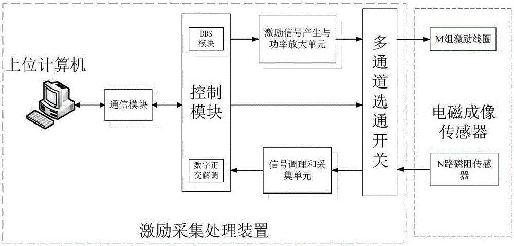
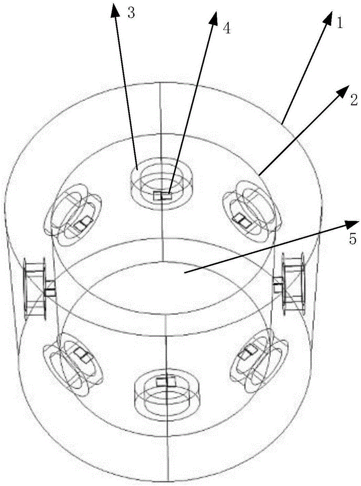
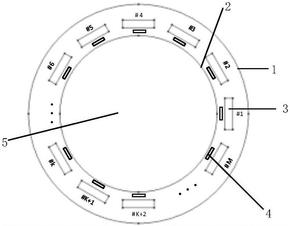
[0019] The invention introduces and designs a fluidized electromagnetic tomography magnetoresistive sensor array, which can obtain the magnetic permeability distribution by directly detecting the magnetic field through the magnetic resistance, and realize the measurement of the magnetic permeability distribution parameters and the magnetic permeability imaging. Magnetoresistive sensor, the detection sensitivity is not affected by the frequency of the excitation magnetic field, which greatly improves the scope of application. At the same time, it is favored by more and more people because of its advantages of high sensitivity, good reliability, wide measurement range, resistance to harsh environments, and small size. . This system introduces a magnetoresistive sensor, due to its small size, generally within 5mm, it can realize the direct detection of the radial and tangential directions of the magnetic field, increase the number of detection points, improve the detection sensiti...


PUM


Abstract

The invention relates to a magneto resistance sensor-based magnetic conductivity electromagnetic tomography system. An electromagnetic imaging sensor is adopted as the sensor of the magneto resistance sensor-based magnetic permeability tomography system; the electromagnetic imaging sensor comprises M excitation coils, N pairs of magneto resistance sensors and an electromagnetic shielding layer, wherein the excitation coils and the magneto resistance sensors are arranged in the electromagnetic shielding layer; each excitation coil is provided with a separate excitation channel; the excitation coils are arranged on the same section outside a cylindrical object field region; the magneto resistance sensor pairs are also arranged on the same section; the excitation coils and the magneto resistance sensors are arranged on different circles; and each pair of magneto resistance sensors is located inside a certain excitation coil. Under the control of a control module, an excitation signal generation and power amplification unit generates excitation signals with different amplitudes and frequencies; the excitation signals are connected onto the designated excitation coils through a multi-channel gating switch; signals outputted by the magneto resistance sensors pass through the gating switch and are transmitted to the control module through a signal conditioning and acquisition unit; the control module demodulates the signals; and the demodulate signals are transmitted to an upper computer through a communication module.

Description

technical field [0001] The invention belongs to the field of multiphase fluid imaging of fluidization technology, in particular to a magnetic permeability electric tomography imaging device. Background technique [0002] Fluidization technology has very high heat and mass transfer efficiency and the ability to handle a large number of particles, and has been widely used in the combustion of solid fuels, coal gasification and coking, solid material transportation, gas and solid in chemical production Phase catalytic reaction, material drying, heating and cooling, petroleum cracking, metallurgy, environmental protection and other fields, and its application field is still expanding. [0003] Multi-phase identification is very important in the multi-phase fluidization process, especially the identification of solid-phase catalysts and the monitoring of distribution state can effectively avoid abnormal fluidization states such as large bubbles, surges and channeling, improve pro...

Claims


Application Information

Patent Timeline
Patent Type & Authority Applications(China)
IPC IPC(8): G01R33/12G01N27/74
CPCG01N27/74G01R33/1223
Inventor 白瑞峰王超崔自强
Owner TIANJIN UNIV
Why Eureka
Try Eureka