Electrical motor device
A technology of electric motors and rotating electrical machines, applied in the direction of AC motor control, motor starting for engines, engine components, etc., which can solve the problems of reducing the cost and miniaturization of the motor device without directly stating the outline
- Summary
- Abstract
- Description
- Claims
- Application Information
AI Technical Summary
Problems solved by technology
Method used
Image

Examples
no. 1 Embodiment
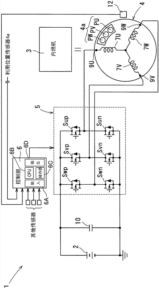
[0042] use figure 1 The structure of the motor device 1 of the first embodiment will be described.
[0043] An electric motor device (hereinafter, referred to as a system) 1 is provided in a vehicle, and uses power supplied from an on-vehicle battery (hereinafter, simply referred to as a battery 2 ) to generate an output to start an internal combustion engine 3 , or assist the output of the internal combustion engine 3 , or utilize the output of the internal combustion engine 3 The voltage induced by the driving force charges the battery 2 , and the motor device 1 functions as both a motor and a generator.
[0044] Furthermore, the system 1 includes the following rotary electric machine 4 , inverter 5 , and control unit (functioning as a control means) 6 .
[0045] First, the rotary electric machine 4 operates as an electric motor that starts the internal combustion engine 3 or assists the output of the internal combustion engine 3 , or operates as a generator that charges th...
no. 2 Embodiment
[0081] The system 1 of the second embodiment is adopted. In this second embodiment, the description will focus on the configurations different from the system 1 of the first embodiment, and the same reference numerals will be used for the same configurations as those described in the first embodiment, and the description will be omitted or simplified. .
[0082] Adopt the system 1 of the 2nd embodiment, as Figure 5 As shown, by providing center taps 8U, 8V, and 8W in windings 7U to 7W, the actual number of turns for each phase can be varied.
[0083] In addition, the actual number of turns is the number of turns of the part of each of the windings 7U to 7W that is energized by the power supply from the battery 2 during the operation as a motor, or the number of turns that transmits the induced voltage to the battery 2 during the operation as a generator. number of turns supplied by the part.
[0084]Therefore, in the windings 7U to 7W of the rotating electrical machine 4 ,...
no. 3 Embodiment
[0134] The system 1 of the third embodiment will be described. In this third embodiment, the description will focus on the configurations different from the system 1 of the second embodiment, and the same symbols will be used for the configurations that are the same as those described in the second embodiment, and the description will be omitted or simplified.
[0135] In the control unit 6 of the system 1 of the third embodiment, as Figure 12 As shown, the functions of the control unit 6 are provided by the CPU 6B reading the control program of the third embodiment in the memory 6C and executing the program. This function also includes a stroke determination unit 17 ( Figure 12 : Functions as a process judgment part). Stroke determination unit 17 , that is, control unit 3 , determines the stroke of internal combustion engine 3 using, for example, a signal output from rotational speed detector 12 (signal indicating crank angle) and a signal indicating intake pressure of in...
PUM
 Abstract
Description
Claims
Application Information
 - R&D
- Intellectual Property
- Life Sciences
- Materials
- Tech Scout
- Unparalleled Data Quality
- Higher Quality Content
- 60% Fewer Hallucinations
Browse by: Latest US Patents, China's latest patents, Technical Efficacy Thesaurus, Application Domain, Technology Topic, Popular Technical Reports.
© 2025 PatSnap. All rights reserved.Legal|Privacy policy|Modern Slavery Act Transparency Statement|Sitemap|About US| Contact US: help@patsnap.com