Porous ammonia spraying device used for W-flame boiler high-temperature reduction zone

A boiler and flame technology, which is applied in the field of porous ammonia injection devices, can solve the problems of low out-of-stock efficiency and high emission, and achieve the effects of high out-of-stock efficiency, increased contact and mixing degree, and small dosage

Active Publication Date: 2018-01-05
HARBIN INST OF TECH
View PDF8 Cites 8 Cited by
  • Summary
  • Abstract
  • Description
  • Claims
  • Application Information

AI Technical Summary

Problems solved by technology

[0007] The present invention is to solve existing swirl burner W flame boiler to exist NO x To solve the problems of high emission and

Method used


Image

  • Porous ammonia spraying device used for W-flame boiler high-temperature reduction zone
  • Porous ammonia spraying device used for W-flame boiler high-temperature reduction zone

Examples


specific Embodiment approach 1

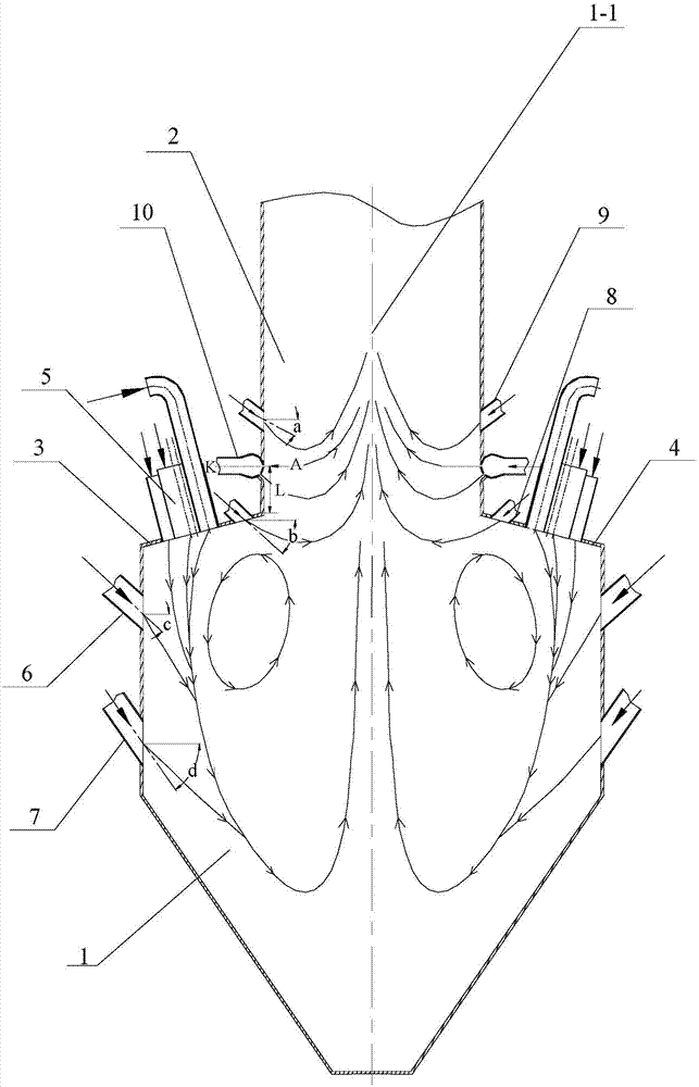
[0024] Specific implementation mode one: as Figure 1~2As shown, the porous ammonia injection device used in the high-temperature reduction zone of the W flame boiler in this embodiment, wherein the W flame boiler includes a furnace consisting of a lower furnace 1, an upper furnace 2, a front furnace arch 3 and a rear furnace arch 4, and a plurality of The swirling pulverized coal burners 5 biased by the secondary air are distributed in a line along the width direction of the furnace respectively, and the swirling pulverized coal burners 5 on the front furnace arch 3 and the rear furnace arch 4 Symmetrically arranged, the porous ammonia spraying device includes a plurality of porous ammonia spraying devices 10, the porous ammonia spraying device 10 is a hollow sphere, and the upper part of the front side wall of the lower furnace 1 is sequentially arranged with a plurality of swingable exhaust air nozzles along the horizontal direction 6. The middle part of the front side wall...

specific Embodiment approach 2

[0025] Specific implementation mode two: as figure 1 As shown, the porous ammonia injection device 10 of this embodiment is arranged in the area above the furnace throat and below the swingable second-stage burn-off air nozzle 9, and the central plane K of the porous ammonia injection device 10 reaches the front furnace arch 3 or the rear furnace arch 4 The upper edge distance L ranges from 0.5m to 2m, the angle between the central plane K of the porous ammonia injection device 10 and the horizontal plane is 0°, and the porous ammonia injection device 10 is set in one-to-one correspondence with the second-stage overburning air nozzle 9, The central planes K of the porous ammonia injection device 10 are located on the same plane. Other components and connections are the same as those in the first embodiment.

specific Embodiment approach 3

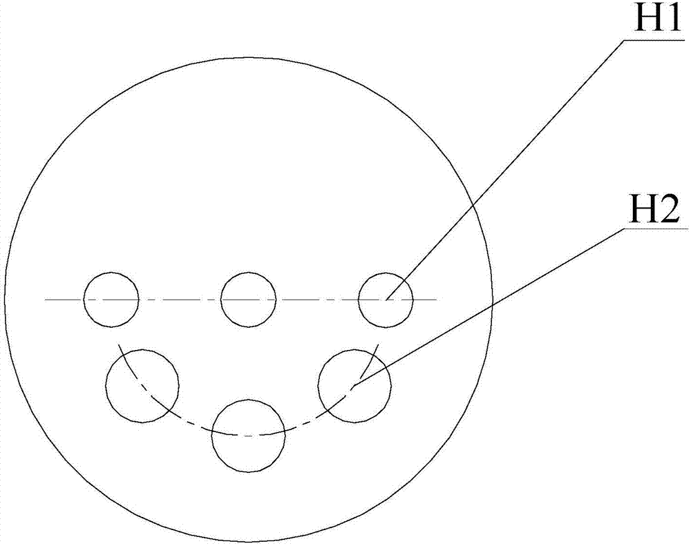
[0026] Specific implementation mode three: as figure 2 As shown, in this embodiment, the circular orifices are distributed in two layers on the hemisphere below the central plane K, the angle between the central plane of the horizontal orifice H1 of the first layer and the horizontal plane is 0°, and the center of the inclined orifice H2 of the second layer The angle between the plane and the horizontal plane is 45°. With this design, the orifices of the porous ammonia injection device are distributed in layers, and the inclined orifices and horizontal orifices realize the single-structure double-layer ammonia injection in the furnace. The ammonia sprayed from the inclined orifices is firstly mixed with the rising flue gas to realize The first layer of ammonia injection reduces NO x , the flue gas continues to rise, and soon mixes with the ammonia sprayed from the horizontal orifice, and again with the NO in the flue gas x A reduction reaction occurs, and the second layer o...


PUM


Abstract

The invention discloses a porous ammonia spraying device used for a W-flame boiler high-temperature reduction zone and relates to porous ammonia spraying devices. The problems that an existing turbulent burner W-flame boiler is high in NOx emission and low in denitration efficiency are solved. The porous ammonia spraying devices are hollow spheres; a plurality of swinging exhaust air spraying nozzles are sequentially arranged on the upper portion of the front side wall of a lower hearth in the horizontal direction; a plurality of swinging graded air spraying nozzles are sequentially arranged in the middle of the front side wall of the lower hearth in the horizontal direction; a plurality of swinging first-grade overfire air spraying nozzles are arranged on a rear boiler arch in the horizontal direction; a plurality of swinging second-grade overfire air spraying nozzles are sequentially arranged in the middle of an upper hearth in the circumferential direction; the multiple porous ammonia spraying devices are sequentially arranged on the lower portion of the upper hearth in the circumferential direction and are the hollow spheres; and a plurality of round holes are machined in the positions, below the center faces K of the porous ammonia spraying devices, of the spheres, so that multi-azimuth and multi-angle direct ammonia spraying is formed. The porous ammonia spraying device is used for ammonia spraying on the W-flame boiler high-temperature reduction zone.

Description

technical field [0001] The invention relates to a porous ammonia injection device, in particular to a porous ammonia injection device used in a high-temperature reduction zone of a W flame boiler, and belongs to the technical field of W flame boiler combustion. Background technique [0002] W Flame Boiler is a boiler specially designed for burning anthracite and lean coal. This kind of boiler generally NO x Emissions are high. NO x It is toxic to animals and humans, is one of the main substances that form acid rain, is also an important substance that forms photochemical smog in the atmosphere and an important factor that destroys the atmospheric ozone layer. The "Comprehensive Implementation of Ultra-low Emissions and Energy Saving Transformation Work Plan for Coal-fired Power Plants" requires that by 2020, coal-fired power plants will achieve ultra-low emissions, of which NO x Emission concentration is 50mg / m 3 (6%O 2 ), while the W flame boiler with swirl burner NO ...

Claims


Application Information

Patent Timeline
IPC IPC(8): F23C5/08F23C7/00F23L1/00F23L7/00F23L9/02B01D53/78B01D53/79B01D53/56
Inventor 陈智超王青祥王炳楠曾令艳李争起张鑫
Owner HARBIN INST OF TECH
Why Eureka
Try Eureka