M-phase stator winding switch reluctance motor, driving method and pole-changing method

A technology of switched reluctance motor and stator winding, which is applied in the direction of AC motor control, connection with control/drive circuit, electrical components, etc., and can solve problems such as increased control complexity, easy slipping of conductors in the slot, and reduced motor performance , to achieve the effect of easy driving mode, high slot full rate, and fewer outlets

Pending Publication Date: 2018-01-05
HENAN POLYTECHNIC UNIV +1
View PDF7 Cites 2 Cited by
  • Summary
  • Abstract
  • Description
  • Claims
  • Application Information

AI Technical Summary

Problems solved by technology

For the traditional switched reluctance motor, the stator has evenly distributed salient poles in the circumferential direction, and windings are wound on the salient poles. The slot formed by the adjacent salient poles has a large width, and the conductor in the slot is easy to slip out, which is unsafe.
The winding adopts a concentrated coil structure. During the winding process, the space of the winding mechanism must be reserved, resulting in a low slot full rate, a decline in motor performance, and a large motor volume.
At the same time, the simple and easy pole-changing speed regulation method is of great significance to the application and development of motors. For general induction motors, the pole-changing speed regulation needs to change the wiring of each phase winding of the stator, or use two sets of independent windings. The core and dimensions of the motor with this structure are generally larger than the ordinary induction motor with the same capacity, and there are more outlets, and a changeover switch needs to be installed, which increases the complexity of control

Method used


Image

  • M-phase stator winding switch reluctance motor, driving method and pole-changing method
  • M-phase stator winding switch reluctance motor, driving method and pole-changing method
  • M-phase stator winding switch reluctance motor, driving method and pole-changing method

Examples


Embodiment 1

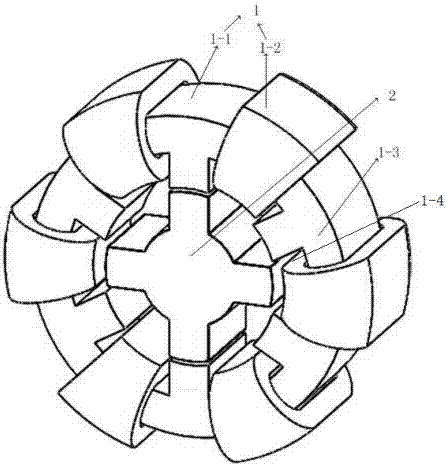
[0032] Such as figure 1 figure 2 image 3 A three-phase stator winding switched reluctance motor, including a stator 1 and a rotor 2, and a drive unit, the stator 1 includes a stator core 1-1 and a stator winding, the rotor 2 is arranged inside the stator 1; the stator core 1- The inner surface of 1 is evenly opened with 6 coil slots 1-4; the stator winding is composed of 6 coils 1-2, which are respectively wound on the stator yoke 1-3 of the stator 1, and each of the coils 1-2 2 is set in a coil slot 1-4, and the second coil side is set outside the stator yoke 1-3 on the same radial direction as the coil slot 1-4; each coil 1-2 leads The wires are respectively connected to the output end of a drive unit, and the drive unit can provide forward or reverse current to supply power to each coil 1-2 of the stator winding individually.

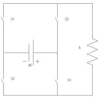
[0033] Each drive unit is composed of four switching tubes S1, S2, S3, S4 and DC power supply; the DC power supply is connected with the four s...

Embodiment 2

[0036] Such as Figure 1-3 A three-phase toroidal winding switched reluctance motor driving method is shown, taking the three-phase 6 / 4 mechanism as an example,

[0037] The motor clockwise rotation drive steps are as follows:

[0038] A1: Turn on the S2 and S3 switches at the same time, pass the forward current to the a1, b1, c1 windings respectively, pass the reverse current to the a2, b2, c2 windings respectively, generate a magnetic field in the stator, and pass through the stator teeth 101 into the rotor.

[0039] A2: Pass forward current to b1, c1, a2 windings respectively, and pass reverse current to b2, c2, a1 windings respectively, the magnetic field in the stator passes through the stator teeth 102 and enters the rotor.

[0040] A3: Pass forward current to c1, a2 and b2 windings respectively, and pass reverse current to c2, a1 and b1 windings respectively, and the magnetic field in the stator passes through the stator teeth 103 and flows into the rotor.

[0041] T...

Embodiment 3

[0046] A pole-changing method for an m-phase toroidal winding switched reluctance motor. When n connected drive units pass forward or reverse current at the same time, the magnetic circuit of the motor is 2km / n poles, where n is a positive integer, 2km / n is a positive integer.

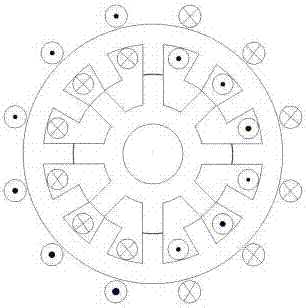
[0047] Take the 12-phase toroidal winding switched reluctance motor as an example: Figure 4 As shown, when there are 6 connected drive units passing forward current at the same time, the motor magnetic circuit is two poles;

[0048] Such as Figure 5 As shown, when there are 3 connected drive units passing forward or reverse current at the same time, the motor has 4 poles; with this rule, the number of poles of the motor can be changed.


PUM


Abstract

The invention discloses an m-phase stator ring winding switch reluctance motor, a driving method and a pole-changing method. The m-phase stator ring winding switch reluctance motor comprises a stator,a rotor and a driving unit. The driving method achieves forward or reverse rotation of the motor by controlling on and off of a switch tube on the driving unit and an electrifying sequence of coils on the motor. According to the pole-changing method, a magnetic path of the motor is 2 km / n poles when forward or reverse current is galvanized to n connected driving units simultaneously, wherein n isa positive integer, and the 2 km / n is a positive integer. The m-phase stator ring winding switch reluctance motor has the advantages that the electrifying sequence and the electrifying time of a stator winding are respectively controlled by the driving unit, and pole-changing speed regulation of the motor is achieved through the control method. Compared with a traditional motor, the structures oftraditional primary and secondary windings are omitted, few winding outgoing lines are adopted, and the m-phase stator ring winding switch reluctance motor has the advantages of being small in size,high in efficiency, easy to control and adjustable and adopting multiple rotation speeds.

Description

technical field [0001] The invention relates to the technical field of design and use of a driving motor, in particular to an m-phase ring-winding switched reluctance motor, a driving method, and a pole-changing method. Background technique [0002] As a high-efficiency and energy-saving motor, the switched reluctance motor has always been favored by people for its future application. For the traditional switched reluctance motor, the stator has evenly distributed salient poles in the circumferential direction, and the windings are wound on the salient poles. The slots formed by the adjacent salient poles are very wide, and the conductors in the slots are easy to slip out, which is not safe. The winding adopts a concentrated coil structure. During the winding process, the space of the winding mechanism must be reserved, resulting in a low slot full rate, a decline in motor performance, and a large motor volume. At the same time, the simple and easy pole-changing speed regul...

Claims


Application Information

Patent Timeline
IPC IPC(8): H02K29/00H02K1/14H02K1/16H02K11/33H02P25/08
CPCY02T10/64
Inventor 司纪凯崔旭李应生时海燕刘群坡封海潮许孝卓
Owner HENAN POLYTECHNIC UNIV
Why Eureka
Try Eureka