Reciprocating motor and reciprocating compressor having the same

A reciprocating, reciprocating motion technology, applied in the direction of machines/engines, liquid variable capacity machinery, electromechanical devices, etc., can solve the problems of increased power consumption, reduced motor efficiency, increased air gap, etc., to reduce friction loss and Effects of noise, reduced number of parts, and increased spring rigidity

Active Publication Date: 2020-05-05
LG ELECTRONICS INC
View PDF9 Cites 0 Cited by
  • Summary
  • Abstract
  • Description
  • Claims
  • Application Information

AI Technical Summary

Problems solved by technology

[0011] However, in the conventional reciprocating motor as described above, there is a problem that although the rotor is supported by a mechanical resonance spring composed of a compression coil spring, self-resonance occurs due to the characteristics of the compression coil spring. Specific intervals within the operating frequency of the interval will not be used as the operating frequency
[0012] And, in the reciprocating motor of the prior art, owing to be provided with the mechanical resonant spring that is made of compression coil spring, will produce the limitation of aspects such as mechanical stress limit and vibration distance on the characteristic of its compression coil spring, thus, It is necessary to ensure the specified wire diameter and length of the resonant spring, so there is a limit to reducing the lateral length of the reciprocating motor
[0013] And, in the reciprocating motor of prior art, owing to be provided with the mechanical resonant spring that is made of compression coil spring, need to be respectively provided with the spring support member that is used to fix the two ends of this compression coil spring on rotor and stator, therefore, not only The mechanical structure of the motor becomes complicated, and it is necessary to press multiple resonance springs with high pressure and arrange them respectively on the front and rear sides of the rotor, making the assembly process correspondingly difficult
[0014] Furthermore, in the conventional reciprocating motor, since a rotor including magnets is reciprocally arranged between the outer stator and the inner stator, air gaps are respectively formed on the outer side and the inner side of the rotor, so that Increased overall air gap reduces motor efficiency
[0015] Moreover, in the prior art reciprocating motor, since the thickness of the magnet frame supporting the magnet is relatively thick, the weight of the rotor as a whole increases, thereby not only increasing the power consumption, but also reducing the air gap between the outer stator and the inner stator. will be further increased, resulting in a further reduction in motor efficiency
[0016] And, in the reciprocating compressor to which the above-mentioned reciprocating motor is applied, there will also be the problems existing in the aforementioned reciprocating motor, and therefore there is a limit in making the reciprocating compressor miniaturized.

Method used


Image

  • Reciprocating motor and reciprocating compressor having the same
  • Reciprocating motor and reciprocating compressor having the same
  • Reciprocating motor and reciprocating compressor having the same

Examples


Embodiment Construction

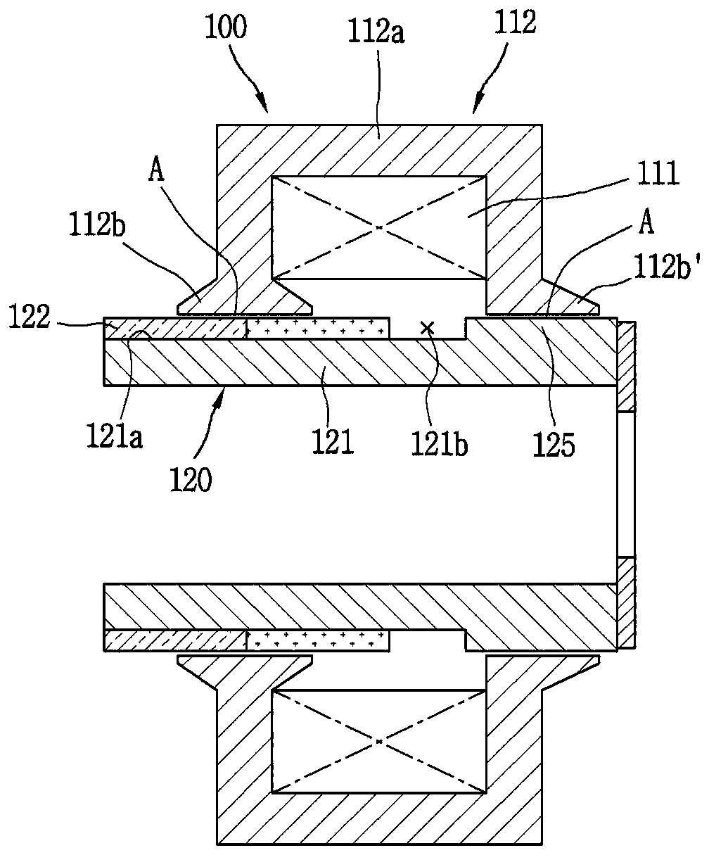
[0063] Hereinafter, a reciprocating motor and a reciprocating compressor including the reciprocating motor according to the present invention will be described in detail based on an embodiment shown in the drawings.

[0064] The reciprocating motor of the present embodiment performs reciprocating motion using a centering force in a reciprocating direction generated between a stator provided with a magnetic coil and a magnet. The central force in the reciprocating direction refers to the force stored in the direction where the magnetic energy (magnetic potential energy, reluctance) is low when the magnet moves in the magnetic field, and this force forms a magnetic spring.

[0065] Therefore, in this embodiment, when the magnet reciprocates using the magnetic force based on the magnetic coil, the magnet accumulates a force to return to the direction of the air gap due to the magnetic spring, and the rotor including the magnet is driven by the force accumulated in the magnetic spr...


PUM


Abstract

The present invention provides a reciprocating motor and a reciprocating compressor having the same. The reciprocating motor of the present invention comprises: a stator provided with a magnetic coil; Air gaps are respectively formed on the two sides; and a rotor is inserted into the stator, at least one magnet is arranged in one of the air gaps on both sides, and a magnetic body other than a magnet is arranged in the other air gap, to reciprocate the rotor relative to the stator.

Description

technical field [0001] The invention relates to a reciprocating motor and a reciprocating compressor thereof, in particular to a reciprocating motor using magnetic energy to resonate a piston and a reciprocating compressor having the same. Background technique [0002] Motor (Motor) is a device that converts electrical energy into mechanical energy to obtain rotational force or reciprocating power. Such motors can be divided into AC motors and DC motors according to the type of power applied. [0003] The motor includes a stator (Stator) and a rotor (Mover or Rotor). Along the direction of the magnetic flux (Flux) generated when a current flows in the coil (Coil) of the stator, the rotor equipped with a magnet (Magnet) performs rotary motion or reciprocating motion. [0004] Motors can be classified as rotary motors or reciprocating motors according to the way the rotor moves. Rotary motors use a method in which magnetic flux is formed on the stator according to the power ...

Claims


Application Information

Patent Timeline
Patent Type & Authority Patents(China)
IPC IPC(8): H02K33/18
CPCF04B35/045H02K3/16H02K33/16F04B35/04F04B39/0005F04B39/10F04B39/12
Inventor 郑相燮权五昌朴贞植李钟九
Owner LG ELECTRONICS INC
Why Eureka
Try Eureka