Special-shaped balling resistant PDC drill bit
A technology of mud balls and drill bits, which is applied in the direction of drill bits, drilling equipment, earthwork drilling and production, etc., to achieve good effects of preventing mud balls of drill bits, improving ROP, and ensuring underground safety.
- Summary
- Abstract
- Description
- Claims
- Application Information
AI Technical Summary
Problems solved by technology
Method used
Image

Examples
Embodiment 1
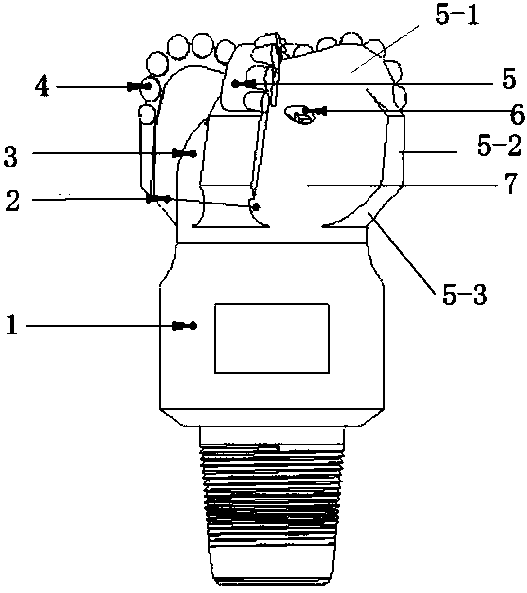
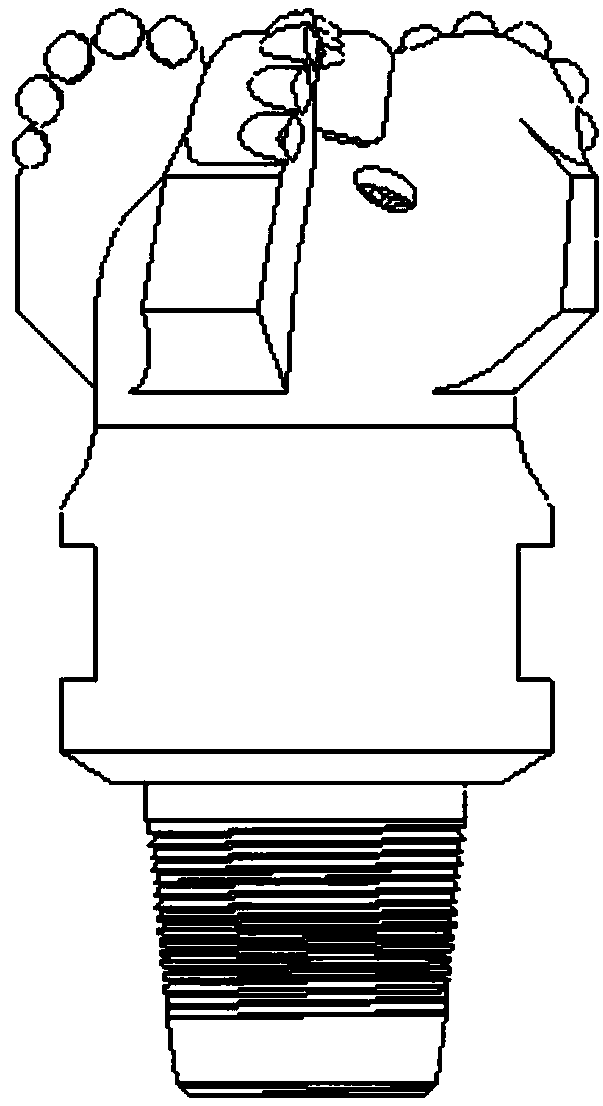
[0027] Such as Figures 1 to 3 As shown, the present embodiment provides a special type of mud-rejecting bag PDC drill bit, which includes a drill bit body 3, a threaded joint 1 located at the lower part of the drill bit body 3 and connected to a drill pipe, and several blades 5 located at the upper part of the drill bit body 3. The groove between the adjacent blades 5 forms a chip removal groove 7, and a composite sheet 4 is installed on each blade 5, and it is characterized in that: one side of each blade 5 is provided with a mud-rejecting groove 2, so The outer edge of the mud-repelling trapping groove 2 starts from the bottom of the composite sheet 4, and the inner edge of the mud-repelling trapping groove 2 ends at the chip removal groove 7.
Embodiment 2
[0029] This embodiment is further optimized on the basis of embodiment 1, specifically:
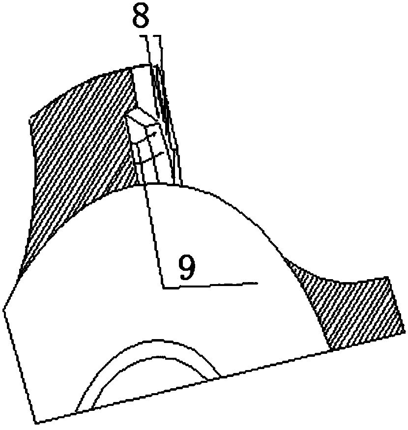
[0030] The blade 5 is composed of an inner cone 5-3, a nose 5-2 and an outer cone 5-1 connected in sequence, and the outer edge of the mud-repelling trap groove 2 is the inner cone 5-3, the nose 5-2 The outline track formed by the outer cone 5-1 is shifted to the lower part of the composite sheet 4 to form the second characteristic surface of the blade from the outer edge of the mud-rejecting trapping groove 2 to the chip removal groove, and the second characteristic faces the working side of the drill bit. Material is removed in the opposite direction to form the mud-repelling trapping groove 2 .
Embodiment 3
[0032] This embodiment has been further optimized on the basis of embodiment 1 or 2, specifically:
[0033] The outer edge of the mud-repelling entrapment groove 2 is formed by offsetting the outline track line formed by the inner cone 5-3, the nose 5-2 and the outer cone 5-1 to the lower part of the composite sheet 4 by 10-20 mm, and the second feature Facing the opposite direction of the drill bit, remove 5-8 mm of material to form the mud-repelling trap groove 2 .
[0034] The drill body 3 is provided with a plurality of nozzles 6 .
[0035] The PDC drill bit with mud-repelling groove can pass the extruded colloidal mudstone through the first surface of the blade at the lower end of the composite sheet at a distance of 10-20mm, then break the contact with the surface of the blade, and form a structure with the second surface of the blade. A certain space forms a suspended state. The mud pump of the main equipment on the ground passes the drilling fluid through the high-pr...
PUM
 Abstract
Description
Claims
Application Information
 - Generate Ideas
- Intellectual Property
- Life Sciences
- Materials
- Tech Scout
- Unparalleled Data Quality
- Higher Quality Content
- 60% Fewer Hallucinations
Browse by: Latest US Patents, China's latest patents, Technical Efficacy Thesaurus, Application Domain, Technology Topic, Popular Technical Reports.
© 2025 PatSnap. All rights reserved.Legal|Privacy policy|Modern Slavery Act Transparency Statement|Sitemap|About US| Contact US: help@patsnap.com