Engine lubricating system and engine

A lubrication system and engine technology, which is applied in the direction of engine lubrication, engine components, machines/engines, etc., can solve the problems of reducing system reliability and safety, increasing the complexity of the shaft drive system, and the oil return pump cannot be smaller than the main oil pump. Achieve the effect of light weight, less parts, and reduce the pressure of space layout

Pending Publication Date: 2018-01-09
芜湖钻石航空发动机有限公司
View PDF12 Cites 6 Cited by
  • Summary
  • Abstract
  • Description
  • Claims
  • Application Information

AI Technical Summary

Problems solved by technology

With the development of the domestic general aviation market, there are more and more cases of applying the traditional automotive lubrication system to the aviation piston engine. However, because the traditional engine generally uses a wet oil pan, the inclination angle of the engine will affect the lubricating oil pump. Normal oil absorption, at the same time, the angle is too large to cause oil stirring and increase friction loss. Therefore, the use of traditional piston engines limits the performance of the aircraft to a certain extent, increases the difficulty of aircraft layout, and limits the flight angle of the aircraft.
[0003] In the prior art, for example, the patent number is 201420393496.9, and the patent title is the engine lubrication system, the engine and the vehicle. The patent is realized by setting a separate oil return pump. improved, but the technical solution in this invention requires that the performance of the oil return pump should at least not be less than that of the main oil pump, and a separate set of drive shaft system is required, which not only increases the weight of the shaft and the complexity of the drive system, but also increases the return The weight of the oil pump, from the perspective of the aircraft, adding a drive system is equivalent to reducing the reliability and safety of the system, and increasing the weight of the engine is equivalent to weakening the competitive advantage of the engine

Method used


Image

  • Engine lubricating system and engine

Examples


Embodiment Construction

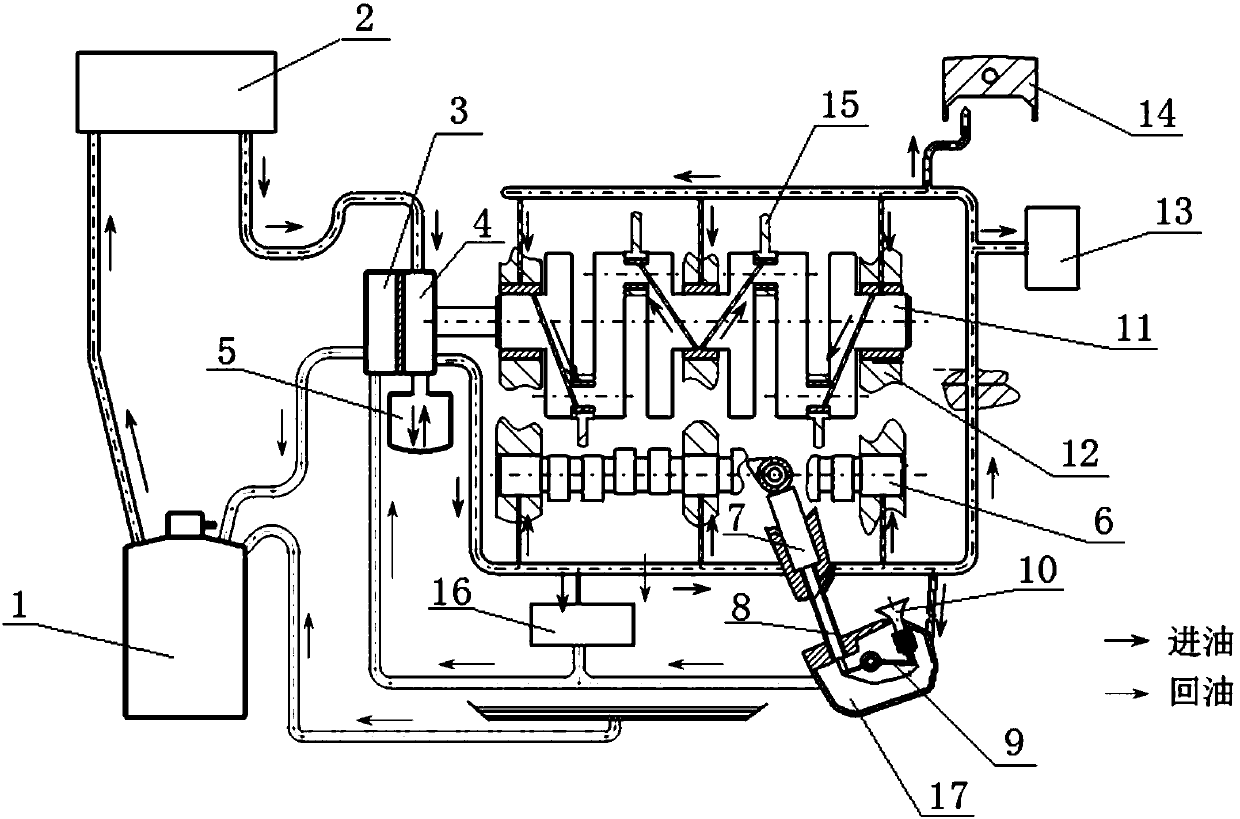
[0019] figure 1 It is a schematic diagram of the engine lubrication system of the present invention. This engine lubrication system includes two parts: oil suction and oil return. At one end of the crankshaft 11, the main oil pump 4, driven by the crankshaft 11, sucks the lubricating oil in the lubricating oil tank 1 into the air-cooled oil cooler 2 for cooling, and the cooled lubricating oil enters the main oil passage under the action of the main oil pump 4 , the lubricating oil entering the main oil passage is divided into five parts, the first part enters the crankshaft 11 main journal, the camshaft 6 journal and the connecting rod 15 journal through the inclined oil passage, the second part enters the hydraulic tappet 7 through the main oil passage, Along the gap between the outer tube of the tappet 8 and the tappet, it enters the corresponding friction part of the rocker arm 9, and the third part of lubricating oil enters the valve cover 17 from the main oil passage thro...


PUM


Abstract

The invention discloses an engine lubricating system and an engine. The engine lubricating system comprises two parts, namely oil suction part and oil return part; the oil suction part comprises a lubricating oil tank, an air cooling oil cooler and a main oil pump which are connected in sequence, the main oil pump sucks the lubricating oil in the lubricating oil tank into the air cooling oil cooler to be cooled under the driving of a crankshaft, and the cooled lubricating oil enters the main oil passage under the action of the main oil pump; the oil return part comprises two parts, the first part is as follow: the lubricating oil entering a piston cooling nozzle, a main bearing, a camshaft bearing and an accessory system flows back to a dry-type oil sump under the action of gravity, and the lubricating flowing back to the dry-type oil sump is pressed back to the lubricating oil tank under the action of the air pressure of a crankcase; and the second part is as follow: the lubricating oil entering a supercharger and a valve cover of the air valve is sucked back to the lubricating oil tank under the action of an oil return pump and through an external oil return pipe. According to the engine lubricating system and the engine, the oil can be directly taken out from the lubricating oil tank by a lubricating oil pump, the situation that the oil cannot be sucked is avoided, limitation on the flying angle of a aircraft is small, the aircraft can do more actions, and flight performance is improved.

Description

technical field [0001] The invention relates to an engine lubricating system, in particular to an engine lubricating system with high efficiency, compactness and light weight. Background technique [0002] Existing piston engines generally use a wet oil pan to store lubricating oil. The working process is generally to suck the lubricating oil from the bottom of the oil pan through the lubricating oil pump, and then pump it to the friction surface of the engine that needs to be lubricated. Finally, the lubricating oil is in the Under the action of gravity, it flows back to the oil pan at the bottom of the engine. With the development of the domestic general aviation market, there are more and more cases of applying the traditional automotive lubrication system to the aviation piston engine. However, because the traditional engine generally uses a wet oil pan, the inclination angle of the engine will affect the lubricating oil pump. Normal oil absorption, at the same time, ex...

Claims


Application Information

Patent Timeline
Patent Type & Authority Applications(China)
IPC IPC(8): F01M1/06F01M11/03
Inventor 熊骏华郑君刘刚胡崇波黄夫龙侯尊周昊洪楠余凯璐周佳
Owner 芜湖钻石航空发动机有限公司
Why Eureka
Try Eureka