Liquid-liquid separation method constructed by cylindrical soil surface force field differences

A solid surface, differential technology, applied in separation methods, liquid separation, chemical instruments and methods, etc., can solve problems such as device blockage, achieve the effect of increasing the separation area and increasing the separation effect

Active Publication Date: 2018-01-12
WUHAN INSTITUTE OF TECHNOLOGY +1
View PDF2 Cites 2 Cited by
  • Summary
  • Abstract
  • Description
  • Claims
  • Application Information

AI Technical Summary

Problems solved by technology

This process only uses the hydrophilic surface of the fiber to coalesce the water phase. In the actual application proc

Method used


Image

  • Liquid-liquid separation method constructed by cylindrical soil surface force field differences

Examples


Embodiment 1

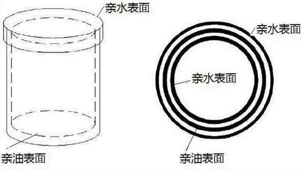
[0030] A copper cylinder is used for the tube material A, and it is placed in NaOH and K 2 S 2 O 8 After soaking in the solution, a uniform needle-like copper hydroxide film is formed on the Cu surface, and then soaked in an ethanol solution of n-dodecyl mercaptan to obtain a copper cylinder with superhydrophobicity and superlipophilicity. The contact angle of the copper cylinder with water is 151°.

[0031] The cylinder material B is a stainless steel cylinder, and the surface is coated with a thermosetting resin solution. After the solvent evaporates, the silicon carbide powder is sprayed on the surface, heated and solidified to form a silicon carbide hydrophilic and oleophobic surface coating.

[0032] According to the technical principles and schemes of this patent, the cylinders A and B after surface modification are figure 1 Relatively arranged, the spacing is between 1um ~ 1000um, preferably 100um, allowing the oil-water mixture to pass between the cylinders A and B. Due to ...

Embodiment 2

[0034] A copper cylinder is used for the tube material A, which is etched with 4mol / L nitric acid solution for 4min, and then soaked in hexadecyl mercaptan with a concentration of 1mmol / L for 1hr to make superhydrophobic and super lipophilic copper The contact angle of the net, copper cylinder and water is kept above 150°.

[0035] The cylinder material B is a stainless steel cylinder, and the surface is coated with a thermosetting resin solution. After the solvent evaporates, the surface of the silica powder is sprayed and heated to cure to form a silica hydrophilic and oleophobic surface coating.

[0036] According to the technical principles and schemes of this patent, the cylinders A and B after surface modification are figure 1 Relatively arranged, the spacing is between 1um~1000um, preferably 200um, allowing the oil-water mixture to pass between the cylinders A and B. Due to the difference in the force field between the surface of A and B on the surface of the oil and water, ...

Embodiment 3

[0038] A stainless steel cylinder is used as the tube material A, and a layer of vertically arranged carbon nanotubes is deposited on the stainless steel by thermal chemical vapor deposition. Because the carbon nanotubes are hydrophobic, they have superhydrophobicity.

[0039] The cylinder material B is an ABS resin cylinder and sprayed on its surface with a polyvinylpyrrolidone solution to form a hydrophilic and oleophobic surface coating.

[0040] According to the technical principles and schemes of this patent, the cylinders A and B after surface modification are figure 1 Relatively arranged, the spacing is between 1um~1000um, preferably 500um, allowing the oil-water mixture to pass between the cylinders A and B. Due to the difference in the force field between the surface of A and B on the surface of the oil and water, different adhesion forces are generated, and the passing Liquid and static to achieve oil-water separation.


PUM


Abstract

The invention discloses a liquid-liquid separation method constructed by cylindrical soil surface force field differences. The liquid-liquid separation method comprises the following steps: enabling ato-be-separated oil-water mixed solution to flow through a gap between a cylindrical material A and a cylindrical material B, wherein the surfaces of the cylindrical material A and the cylindrical material B respectively have lipophilic-hydrophobic property and hydrophilic-oleophobic property; producing different adhesive force by virtue of the surface force field differences of the surfaces of the cylindrical material A and the cylindrical material B to the oil-water mixed solution, collecting the passing liquid, and standing, thereby realizing oil-water separation. The separation method disclosed by the invention comprises a coalescence and separation process of a dispersion phase and further comprises a coalescence and separation process of a continuous phase, so that the separation time is shortened, the separation effect is improved, and the method has excellent effects in the oil-water separation process, a demulsification process and an extraction process.

Description

Technical field [0001] The invention specifically relates to a liquid-liquid separation method constructed by the difference in the force field of the cylindrical solid surface. Background technique [0002] The various physical and chemical changes that occur in the process of material preparation and use are gradually carried out from the surface of the material to the inside of the material. The progress of these processes all depend on the surface structure and properties of the material. The various materials that people usually encounter and use are limited in size, that is, the surface of the material is always exposed in the medium in contact with it. A series of physical and chemical actions occur faster or slower on the contacting interface. The root cause of the surface phenomenon is that the arrangement of particles on the surface of the material is different from the inside of the material, and the surface of the material is in a high-energy state. [0003] The solid...

Claims


Application Information

Patent Timeline
IPC IPC(8): B01D17/022
Inventor 袁军马晓梦陈钱程健张富青
Owner WUHAN INSTITUTE OF TECHNOLOGY
Why Eureka
Try Eureka