Coal-fired flue gas denitration and desulfurization method

A technology for coal-fired flue gas and denitrification, which is applied in separation methods, chemical instruments and methods, and air quality improvement, and can solve problems such as cumbersome operations, large floor space, and high investment and operation costs

Inactive Publication Date: 2018-01-16
HENAN POLYTECHNIC UNIV
View PDF12 Cites 5 Cited by
  • Summary
  • Abstract
  • Description
  • Claims
  • Application Information

AI Technical Summary

Problems solved by technology

[0005] At present, the gypsum method used in industrial flue gas desulfurization and the SCR method used in flue gas denitrification both have high pollutant removal efficiency, but because each pollutant us

Method used


Image

  • Coal-fired flue gas denitration and desulfurization method

Examples


Embodiment 1

[0024] A method for denitrification and desulfurization of coal-fired flue gas provided by the present invention, the coal-fired flue gas is denitrified and desulfurized through the following steps:

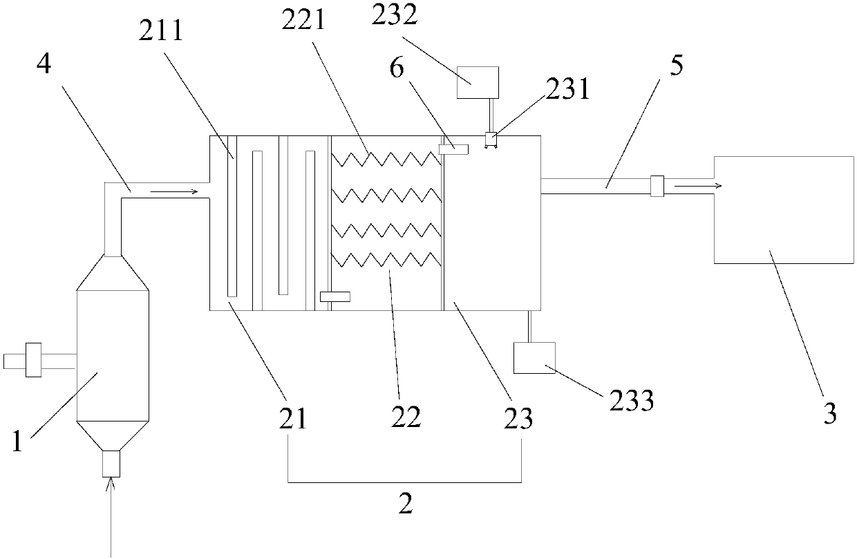
[0025] 1) Pass the coal-burning flue gas into the cyclone 1 for dust removal, and remove dust particles with a particle size greater than or equal to 20um in the flue gas; the purpose is to remove more than 80% of the particle dust in the flue gas;

[0026] 2) The coal-fired flue gas after dust removal enters the desulfurization and denitrification bin 2 to react with denitrification and desulfurization agent and oxygen storage material. The weight ratio of oxygen storage material to denitrification and desulfurization agent is 1:9, and the reaction temperature is 115 °C. 2 and NO X Absorb to obtain preliminary purified flue gas;

[0027] The denitration and desulfurization agent is prepared from the following raw materials in parts by weight: 32 parts of calcium oxide, 20 parts...

Embodiment 2

[0033] A method for denitrification and desulfurization of coal-fired flue gas, wherein the coal-fired flue gas is denitrified and desulfurized through the following steps:

[0034] 1) Pass the coal-burning flue gas into the cyclone 1 for dust removal, and remove dust particles with a particle size greater than or equal to 20um in the flue gas; the purpose is to remove more than 80% of the particle dust in the flue gas;

[0035] 2) The coal-fired flue gas after dust removal enters the desulfurization and denitrification chamber 2 to react with the denitrification and desulfurization agent and the oxygen storage material. 2 and NO X Carry out adsorption to obtain preliminary purified flue gas;

[0036]The denitration and desulfurization agent is prepared from the following raw materials in parts by weight: 45 parts of calcium oxide, 28 parts of manganese dioxide, 18 parts of titanium dioxide, 18 parts of aluminum oxide, and 10 parts of seaweed;

[0037] The oxygen storage mat...


PUM

PropertyMeasurementUnit
Particle sizeaaaaaaaaaa

Abstract

The invention discloses a coal-fired flue gas denitration and desulfurization method and belongs to the field of coal-fired flue gas purification. The coal-fired flue gas denitration and desulfurization method specifically comprises the following steps: introducing coal-fired flue gas into a cyclone cylinder and carrying out dust removal to remove large-particle dust in the flue gas; conveying thedust-removed coal-fired flue gas into a denitration and desulfurization cabin to react with a denitration and desulfurization agent and an oxygen storage material, so as to obtain primarily purifiedflue gas; enabling the primarily purified flue gas to pass through an active carbon fiber net to obtain secondly purified flue gas; then introducing the secondly purified flue gas into a spraying chamber; carrying out absorption treatment on sprayed ammonia water, wherein the absorption temperature is 60 DEG C to 80 DEG C. By adopting the method disclosed by the invention, the reaction speed is improved; independent oxygen supply equipment does not need to be increased so that the equipment cost is reduced; a test shows that the removal rate of SO2 reaches 99.7 percent or more and the removalrate of NOX reaches 98.2 percent or more.

Description

technical field [0001] The invention relates to the field of purification of coal-fired flue gas, in particular to a method for denitrification and desulfurization of coal-fired flue gas. Background technique [0002] SO from coal combustion 2 and NO X It is the main pollutant that causes damage to the atmospheric environment. At present, most coal-fired enterprises are equipped with separate desulfurization and denitrification treatment equipment, but there are many problems in the treatment process, which basically deal with a single pollutant one by one, which leads to the increase of the process chain of flue gas purification, investment and operation costs Increase. [0003] Among the process types of flue gas desulfurization technology in the prior art, the gypsum method is the most commonly used technology in the world. The principle of the gypsum method process is: add limestone powder and water to make a slurry as an absorbent and pump it into the absorption towe...

Claims


Application Information

Patent Timeline
IPC IPC(8): B01D53/81B01D53/60B01D53/78B01D53/56B01D45/16B01D53/04
CPCY02A50/20
Inventor 程敢张传祥路阳张效铭
Owner HENAN POLYTECHNIC UNIV
Why Eureka
Try Eureka