Eccentric rotor engine and combusting and working method thereof
An eccentric rotor and engine technology, applied in combustion engines, machines/engines, internal combustion piston engines, etc., can solve problems such as high emissions, loud engine noise, and complex design
- Summary
- Abstract
- Description
- Claims
- Application Information
AI Technical Summary
Problems solved by technology
Method used
Image
Examples
Embodiment 1
[0039] Example 1: Four-stroke eccentric rotary engine.
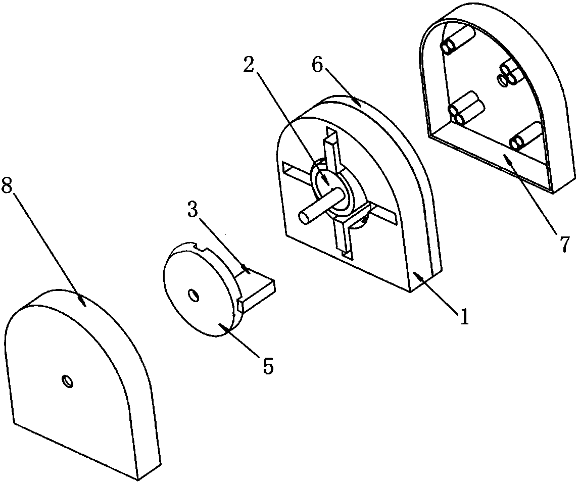
[0040] Such as Picture 1-1 As shown, the present invention mainly includes a cylinder block 1 and an eccentric rotor 2 arranged in the cylinder block 1.
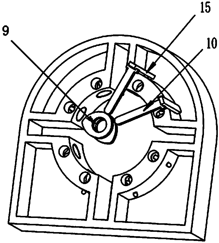
[0041] The cylinder 1 has a cylindrical inner cavity penetrating back and forth for setting the eccentric rotor 2. Such as image 3 As shown, the eccentric rotor 2 includes an eccentric shaft 19, a rotor bearing 17 sleeved on the eccentric shaft 19, and a rotor sealing ring 18 sleeved on the rotor bearing 17, the central axis of the eccentric shaft 19 and the central axis of the cylindrical cavity On the same straight line, the outermost distance of the outer side of the rotor seal ring 18 from the central axis of the eccentric shaft 19 (the maximum rotation radius of the eccentric rotor 2) is slightly smaller than the radius of the inner cavity. When the eccentric rotor 2 rotates, the existence of the rotor bearing 17 can reduce the mechanical wear between the rotor seali...
Embodiment 2
[0048] Embodiment 2: The work method of a four-stroke eccentric rotary engine.
[0049] Taking the four-chamber eccentric rotary engine described in Example 1 as an example, the four chambers are sorted in a clockwise order, namely A, B, C, D, and the upper left chamber is chamber A. Assuming that the center of the movable partition 3 between the chamber A and the chamber B is the 0° position of the cylinder 1, the operating angle of the eccentric rotor 2 refers to the distance between the outer side of the rotor sealing ring 18 of the eccentric rotor 2 and the eccentric shaft 19 The angle corresponding to the most distal point of the axis on the cylinder 1. The working method is as follows (the working procedures of A, B, C, and D chambers are the same and not related to each other. The following only describes the working process of chamber A. The figure does not show the inlet valves and inlets of chambers C and D. Exhaust valve).
[0050] The initial driving force drives the ...
Embodiment 3
[0056] Example 3: Four-stroke continuous combustion eccentric rotary engine.
[0057] The structure of the engine is based on the engine described in Embodiment 1, and is obtained by improving the motion control method of the movable partition 3 and the number of spark plugs.
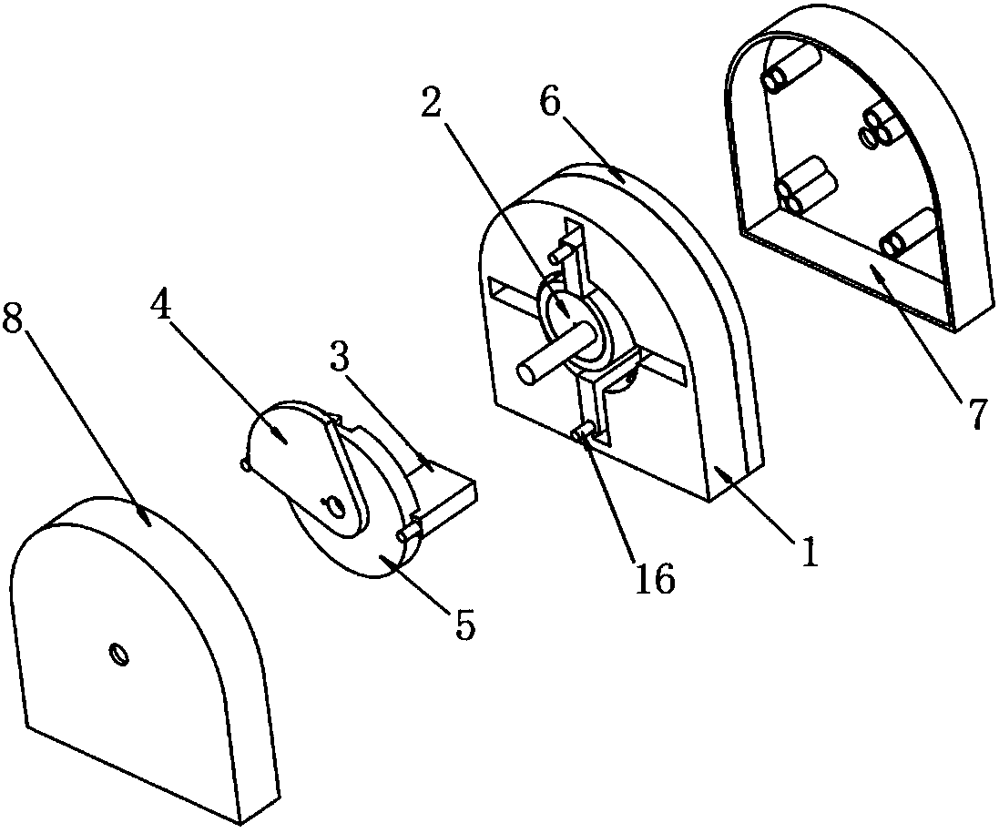
[0058] Such as Figure 5-1 As shown, a spark plug is provided in the upper left chamber, which is an ignition chamber, and no spark plug is required in the remaining chambers. The movable partition 3 located on the side of the intake door 12 of the ignition chamber is a closed partition, which always contacts the rotor sealing ring 18, and the remaining movable partitions 3 are all openable partitions. A pin shaft 16 perpendicular to the front end surface is provided on the front end face of the outer end of the openable partition, and a partition guide plate 4 (such as a partition guide plate 4) is provided on the eccentric shaft 19 between the cavity cover 5 and the front end cover 8. Figure 1-2 ), the pa...
PUM
 Abstract
Description
Claims
Application Information
 - R&D
- Intellectual Property
- Life Sciences
- Materials
- Tech Scout
- Unparalleled Data Quality
- Higher Quality Content
- 60% Fewer Hallucinations
Browse by: Latest US Patents, China's latest patents, Technical Efficacy Thesaurus, Application Domain, Technology Topic, Popular Technical Reports.
© 2025 PatSnap. All rights reserved.Legal|Privacy policy|Modern Slavery Act Transparency Statement|Sitemap|About US| Contact US: help@patsnap.com


