
Time-frequency domain deconvolution method on basis of Gaussian smoothing

A Gaussian smoothing and deconvolution technology, applied in the field of petroleum seismic exploration, can solve the problems of fat wavelet amplitude spectrum, low calculation efficiency, energy dissipation, etc. Effect

Active Publication Date: 2018-01-19
CHINA NAT OFFSHORE OIL CORP +1
View PDF2 Cites 3 Cited by
  • Summary
  • Abstract
  • Description
  • Claims
  • Application Information

AI Technical Summary

Problems solved by technology

The deconvolution model was first proposed by Robinson. It assumes that the reflection coefficient of the formation satisfies the white spectrum characteristics and the seismic wavelet is the minimum phase. On this basis, the traditional deconvolution model is established. The traditional deconvolution model is Based on the premise that there is no loss of energy and the waveform remains unchanged during the propagation of seismic waves underground, the actual seismic waves will be affected by the underground medium during the propagation process, resulting in energy dissipation and velocity dispersion, and the main frequency will follow the propagation. The time increases and shifts to low frequency, and the traditional deconvolution model cannot fit this dynamic process
In order to be more consistent with the actual seismic wave propagation process, considering the ground filtering effect, Margrave converted the seismic records into the Gabor (Gabor) domain, combined with the smoothing function, smoothed the amplitude spectrum of each time window, and directly estimated the attenuation wavelet amplitude spectrum , a time-frequency domain deconvolution method is proposed. This time-frequency domain deconvolution method can improve the resolution of seismic records. However, due to the problem of the smoothing function itself and the fixed time window of the Gabor transform, the deconvolution method has certain limitations
[0003] Traditionally, deconvolution in the frequency domain based on Fourier transform is an important method to improve seismic resolution. However, Fourier transform is a spectral analysis of single-trace seismic records, which can only be mapped in the time domain and frequency domain. The ability to locate the time and frequency of a single-trace seismic record at the same time cannot highlight the local spectral characteristics of a single-trace seismic record. The analysis methods for the time-frequency spectrum of a single-trace seismic record include Gabor transform, wavelet transform, and S transform. However, Gabor transform The defect of fixed time window cannot adapt to the change of time-frequency resolution; wavelet transform needs to make reasonable selection of wavelet base, and the resolution of high frequency area is poor; the basic function of S transform is fixed, and it lacks flexibility in the actual data processing process
[0004] The deconvolution method has developed from static to dynamic, and from frequency domain analysis to time-frequency domain analysis. Although the deconvolution results have been improved, the use of smooth functions in spectrum simulation is greatly disturbed by the data volume. When the polynomial fitting order When it is low, the fitting error is large. When the order is high, the calculation efficiency is low and it is easy to overflow. Using traditional smoothing function fitting will make the wavelet amplitude spectrum "fat", which does not conform to the true shape of the wavelet amplitude spectrum, which will cause deconvolution The result brings errors, which in turn cannot improve the resolution of seismic records and restore the attenuated energy of deep seismic waves

Method used


Image

  • Time-frequency domain deconvolution method on basis of Gaussian smoothing
  • Time-frequency domain deconvolution method on basis of Gaussian smoothing
  • Time-frequency domain deconvolution method on basis of Gaussian smoothing

Examples


Embodiment Construction

[0052] The present invention will be described in detail below in conjunction with the accompanying drawings. However, it should be understood that the accompanying drawings are provided only for better understanding of the present invention, and they should not be construed as limiting the present invention.

[0053] The time-frequency domain deconvolution method based on Gaussian smoothing provided by the present invention comprises the following steps:

[0054] 1. Acquiring seismic data, wherein the seismic data includes multi-channel non-stationary seismic records.

[0055] 2. Based on the Gaussian function and the generalized S-transform, the improved generalized S-transform formula is obtained, and the specific process is as follows:

[0056] S transform is a time-frequency domain analysis method. It absorbs and develops short-time Fourier transform and continuous wavelet transform. Its basic wavelet function is composed of the product of simple harmonic and Gaussian fu...


PUM


Abstract

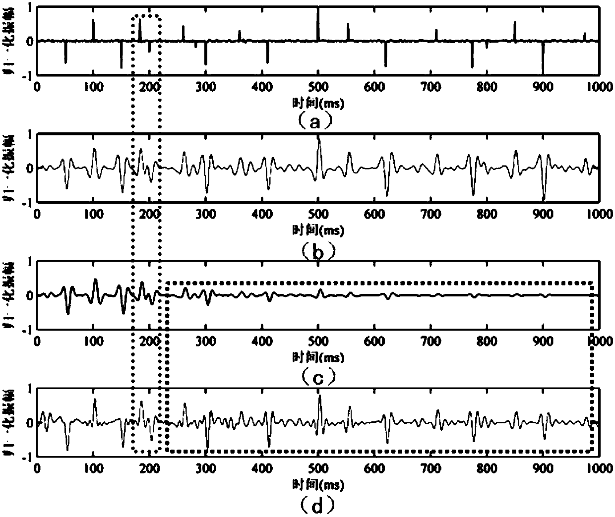
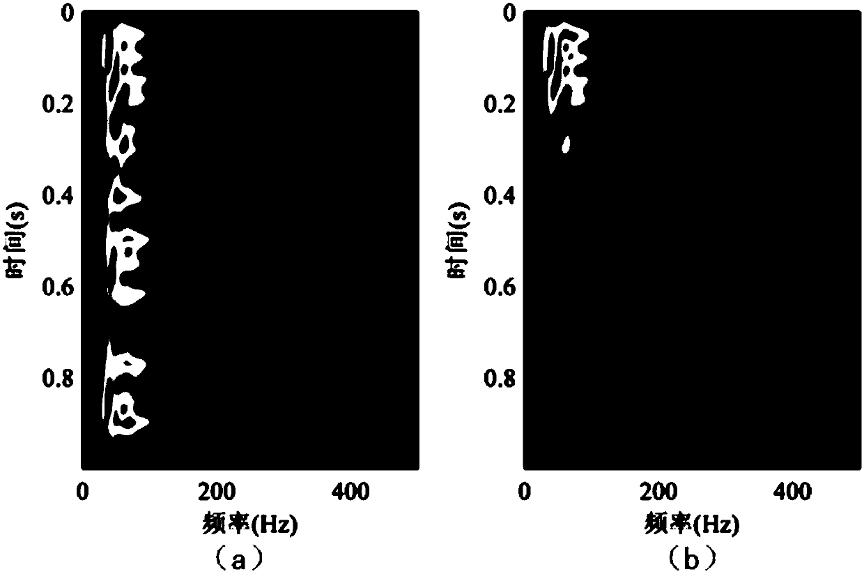
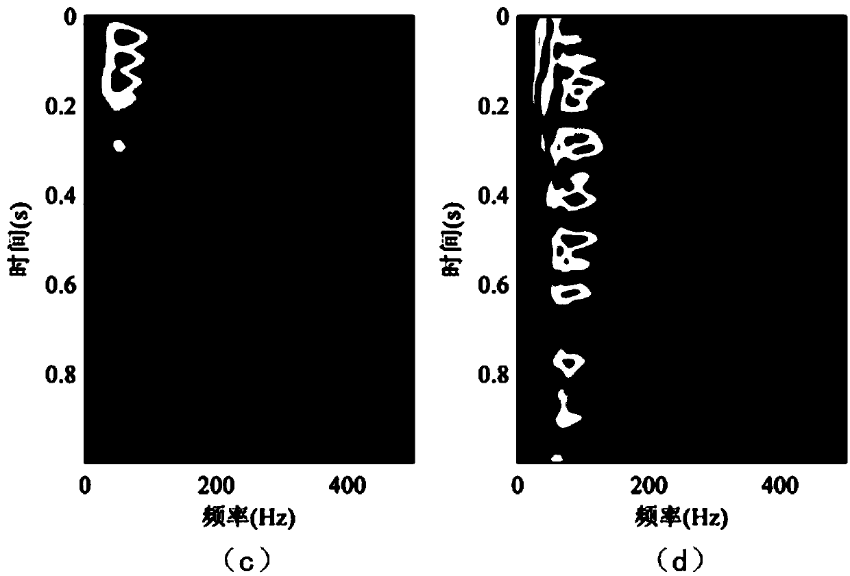
The invention relates to a time-frequency domain deconvolution method on the basis of Gaussian smoothing. The time-frequency domain deconvolution method is characterized by comprising steps of 1), acquiring seismic data with a plurality of non-stationary seismic records; 2), acquiring improved generalized S transformation formulas; 3), selecting certain non-stationary seismic records in the seismic data and setting balance factors of the non-stationary seismic records; 4), carrying out improved generalized S transformation on the non-stationary seismic records to obtain balanced time-frequencyspectra of the non-stationary seismic records; 5), acquiring dynamic wavelet amplitude spectra of the non-stationary seismic records which are already subjected to Gaussian smoothing; 6), acquiring reflection coefficient time-frequency spectra of the non-stationary seismic records; 7), acquiring time-domain reflection coefficients of the non-stationary seismic records; 8), repeatedly carrying outthe steps 3)-7) until time-domain reflection coefficients of all the non-stationary seismic records in the seismic data are solved. The time-frequency domain deconvolution method has the advantage that the time-frequency domain deconvolution method can be widely used in the field of petroleum seismic exploration.

Description

technical field [0001] The invention relates to a time-frequency domain deconvolution method based on Gaussian smoothing, and belongs to the field of petroleum seismic exploration. Background technique [0002] As seismic exploration becomes more and more difficult to accurately describe complex structural reservoirs, the requirements for high resolution and high signal-to-noise ratio of seismic data are also increasing. Deconvolution is used to compress wavelets to improve seismic resolution. The rate method has become one of the most commonly used means. The deconvolution model was first proposed by Robinson. It assumes that the reflection coefficient of the formation satisfies the white spectrum characteristics and the seismic wavelet is the minimum phase. On this basis, the traditional deconvolution model is established. The traditional deconvolution model is Based on the premise that there is no loss of energy and the waveform remains unchanged during the propagation o...

Claims


Application Information

Patent Timeline
IPC IPC(8): G01V1/30
Inventor 刘春成周慰张益明周怀来牛聪施羽黄饶叶云飞
Owner CHINA NAT OFFSHORE OIL CORP
Learn More