A liquid crystal display device

A technology of liquid crystal display and liquid crystal display unit, which is applied in the field of liquid crystal display equipment, can solve the problems of reduced voltage amplitude, difficulty in changing the voltage amplitude of the control driving unit, etc. Effect

Active Publication Date: 2019-11-05
NANJING PANDA ELECTRONICS MFG
View PDF6 Cites 0 Cited by
  • Summary
  • Abstract
  • Description
  • Claims
  • Application Information

AI Technical Summary

Problems solved by technology

Therefore, even if the voltage amplitude does not need to be reduced, the voltage amplitude applied to the pixel by the drive unit is also reduced.
In short, it is difficult to control the voltage amplitude applied to the pixel by the drive unit through the change of the input image signal in the existing technology

Method used


Image

  • A liquid crystal display device
  • A liquid crystal display device
  • A liquid crystal display device

Examples


Embodiment 1

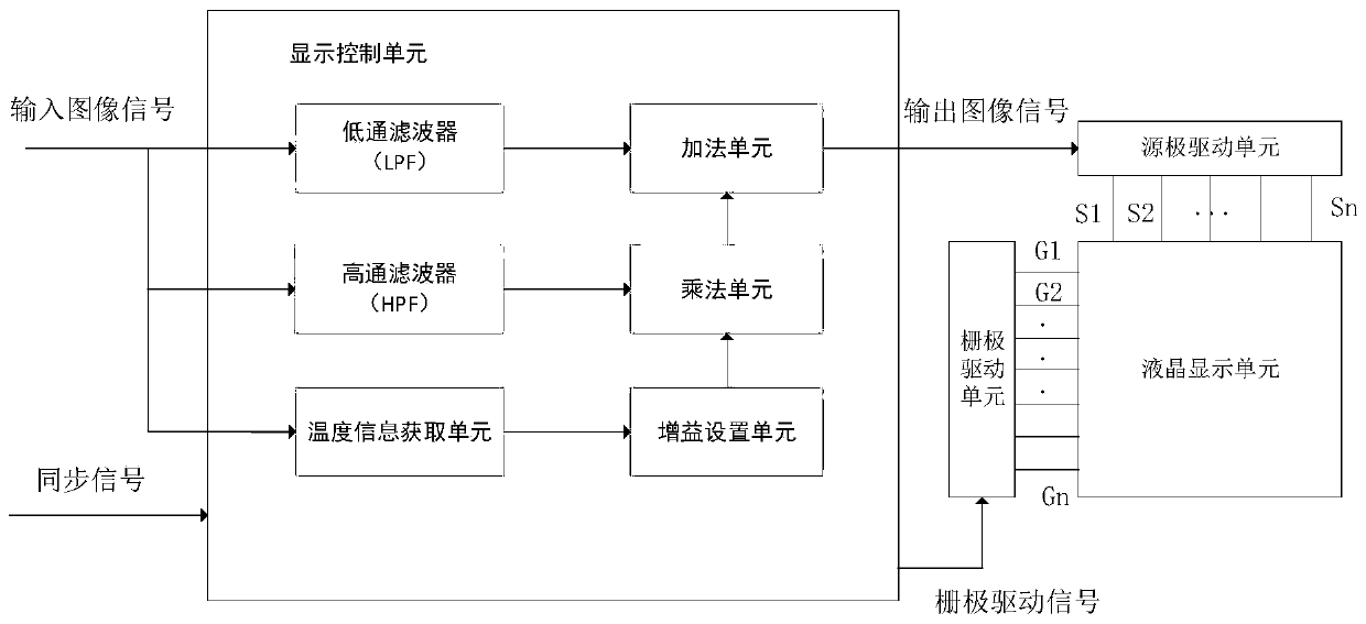
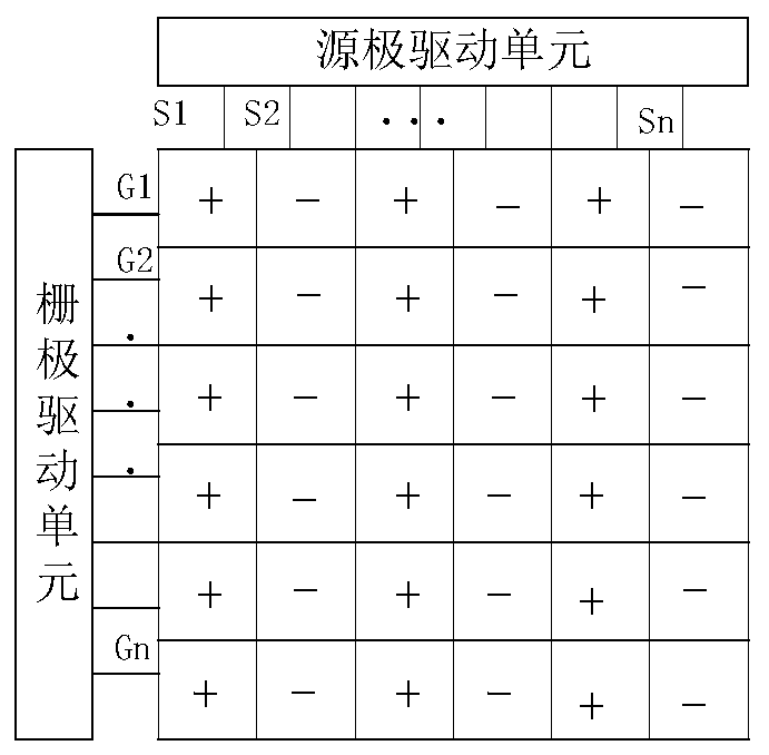
[0032] A liquid crystal display device mainly realizes the control of the driving unit through the control unit to realize the display of the liquid crystal panel. The drive unit includes a source drive unit and a gate drive unit. According to the input image signal and the field synchronization signal, the gate drive unit is controlled to turn on and off the thin film transistor (TFT) row by row through the gate signal line, and cooperate with the source drive The unit applies voltage to the pixel through the source signal line to control the display of the liquid crystal panel. Usually for liquid crystal display, the use of DC voltage driving will cause the liquid crystal molecules to flip in one direction for a long time, which will eventually affect the performance of the liquid crystal panel. effectively solve this problem. In this embodiment, in a certain frame, the polarity of the source signal line S1 is +, and the polarity of S2 is -, and in the next frame, the polar...

Embodiment 2

[0037] A liquid crystal display device includes a liquid crystal display unit, a drive unit and a control unit, wherein the control unit includes a filter unit and a gray scale gain setting unit. The filter unit includes a low-pass filter and a high-pass filter, the low-pass filter obtains the low-frequency component of the input image signal, and outputs the average value of the input image signal level in the vertical direction. The gray scale gain setting unit includes 4 gain curves, namely Gc1~Gc4, such as Figure 10 As shown, the gain curve is preset to correspond to the temperature of the source driver unit and the level of the input image signal. When the temperature T of the source drive unit satisfies the relationship of T Figure 10 As shown, the gain of the gain curve Gcl is a reference gain Gr (Gr=1) that has nothing to do with the signal level of the input image signal. When the input image signal level is the maximum gray scale (8bit is 255) and the minimum gray s...


PUM


Abstract

The invention provides a liquid crystal display device including a liquid crystal display unit, a driving unit and a control unit. A gain setting module is used in the control unit to set the gain according to the temperature of the driving unit, so that the voltage amplitude applied to the pixel of the liquid crystal display unit by a source driving unit is controlled, thereby inhibiting the temperature rise of the source driving unit, improving system performance while ensuring image clarity, and reducing system power consumption.

Description

technical field [0001] The invention belongs to the technical field of liquid crystal display, in particular to a liquid crystal display device. Background technique [0002] In recent years, liquid crystal display devices have been widely used in the display field. The liquid crystal display device mainly applies the pixel voltage to the pixel electrode through the source driving unit, cooperates with the gate driving unit to realize the switching of the TFT to realize the scanning and display of the image. The liquid crystal panel is composed of a plurality of gate scanning lines, source signal lines and a TFT array. The equivalent circuit of the source signal line of the liquid crystal display unit includes line impedance, TFT gate capacitance, capacitance between wiring layers, and capacitance between the wiring layer and the liquid crystal layer. Therefore, in one row period, the change of the input image signal causes the capacitance to be repeatedly charged and disc...

Claims


Application Information

Patent Timeline
Patent Type & Authority Patents(China)
IPC IPC(8): G09G3/36
Inventor 魏伟沈佳洁孙旭杨玉蓉齐学敏
Owner NANJING PANDA ELECTRONICS MFG
Why Eureka
Try Eureka