
Agricultural byproduct dewatering drying machine

A technology for dehydration drying, agricultural and sideline products, applied in dryers, drying, non-progressive dryers, etc., can solve the problems affecting the flavor and quality of dried products, slow production line efficiency, and increase production costs, etc. The effect of reducing baking time, improving production efficiency and extending service life

Inactive Publication Date: 2018-01-23
重庆市六方格农业综合开发有限公司
View PDF0 Cites 13 Cited by
  • Summary
  • Abstract
  • Description
  • Claims
  • Application Information

AI Technical Summary

Problems solved by technology

[0002] The traditional drying equipment for agricultural and sideline products is divided into grain dryers, tobacco leaf drying rooms, and soil kang rooms. The heat energy used is mainly coal, coal, fuel oil, gas and biomass straw. Most of the heat energy utilization rate is low and it is impossible to Renewable energy, some drying rooms, kang rooms, coal or gas, straw smoke and materials collude, affecting the flavor and quality of dried products, some drying rooms, kang rooms, in addition to low heat utilization rate, that is, waste heat is not obtained In addition to recycling, excess energy such as excess humidity, excess cold, and volatile substances have not been recycled and utilized. Some drying equipment, drying rooms, and kang rooms are mostly idle in the off-season due to seasonal restrictions on materials and cannot be dried. For other seasonal agricultural and sideline products, the utilization rate of equipment is low. The traditional dryer does not have dehydration equipment. When the object to be dried is very wet, it takes a long time to dry, which makes the efficiency of the entire production line slow and increases. cost of production

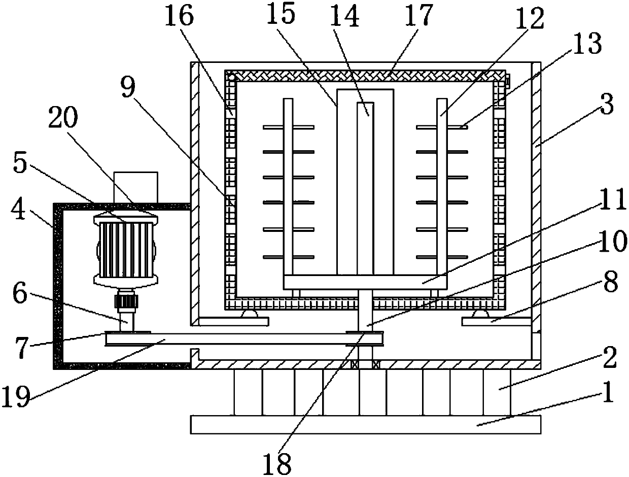
Method used

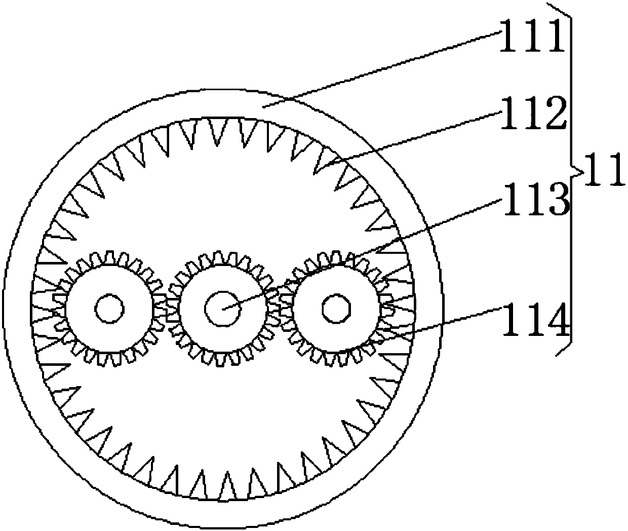
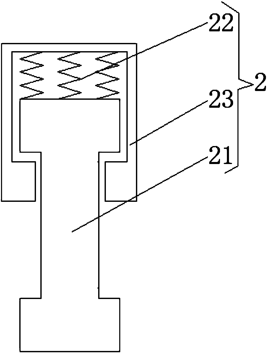

Image

  • Agricultural byproduct dewatering drying machine
  • Agricultural byproduct dewatering drying machine
  • Agricultural byproduct dewatering drying machine

Examples


Embodiment Construction

[0013] The following will clearly and completely describe the technical solutions in the embodiments of the present invention with reference to the accompanying drawings in the embodiments of the present invention. Obviously, the described embodiments are only some of the embodiments of the present invention, not all of them. Based on the embodiments of the present invention, all other embodiments obtained by persons of ordinary skill in the art without making creative efforts belong to the protection scope of the present invention.

[0014] see Figure 1-3 , the present invention provides a technical solution: a dehydration dryer for agricultural and sideline products, including a base 1, the top of the base 1 is fixedly connected with a shock absorber 2, the shock absorber 2 includes a shock absorber 23, and the inner cavity of the shock absorber 23 The top of the top is fixedly connected with a shock absorbing spring 22, and one end of the shock absorbing spring 22 away fro...


PUM


Abstract

The invention discloses an agricultural byproduct dewatering drying machine which comprises a base. A damper is fixedly connected to the top of the base. The damper comprises a damping plate. A damping spring is fixedly connected to the top of an inner cavity of the damping plate. The end, away from the top of the inner cavity, of the damping spring is fixedly connected with a damping rod. The bottom end of the damping rod penetrates the bottom of the damping plate and extends to the outer portion of the damping plate. A box body is fixedly connected to the top of the damping plate. The left side of the box body is fixedly connected with a motor box, and a motor is fixedly connected to the top of an inner cavity of the motor box. By means of the agricultural byproduct dewatering drying machine, due to use of a roller, water on the surfaces of humid agricultural byproducts can be rapidly removed, and the baking time is shortened; and due to use of a stirring rod, the phenomenon that thesurface layer is dry and the inner layer is humid is avoided, the drying quality is ensured, the service life of the machine is prolonged, the production cost is reduced, and the production efficiency is improved.

Description

technical field [0001] The invention relates to the technical field of agricultural product processing, in particular to an agricultural by-product dehydration dryer. Background technique [0002] The traditional drying equipment for agricultural and sideline products is divided into grain dryers, tobacco leaf drying rooms, and soil kang rooms. The heat energy used is mainly coal, coal, fuel oil, gas and biomass straw. Most of the heat energy utilization rate is low and it is impossible to Renewable energy, some drying rooms, kang rooms, coal or gas, straw smoke and materials collude, affecting the flavor and quality of dried products, some drying rooms, kang rooms, in addition to low heat utilization rate, that is, waste heat is not obtained In addition to recycling, excess energy such as excess humidity, excess cold, and volatile substances have not been recycled and utilized. Some drying equipment, drying rooms, and kang rooms are mostly idle in the off-season due to seas...

Claims


Application Information

Patent Timeline
Patent Type & Authority Applications(China)
IPC IPC(8): F26B11/10F26B23/04F26B25/04F26B25/02F26B25/00
Inventor 钟勇
Owner 重庆市六方格农业综合开发有限公司
Learn More