Axial excitation low-speed synchronous motor with axial straight-through tooth integral rotor

A synchronous motor and integral rotor technology, which is applied to synchronous motors with static armatures and rotating magnets, magnetic circuit rotating parts, magnetic circuit static parts, etc. The processing process is cumbersome and the reliability of the motor is reduced.

Inactive Publication Date: 2018-01-23
哈尔滨森特能源科技有限公司
View PDF0 Cites 1 Cited by
  • Summary
  • Abstract
  • Description
  • Claims
  • Application Information

AI Technical Summary

Problems solved by technology

Two adjacent rotor yokes are staggered by half a tooth pitch in the circumferential direction. There are also axial excitation elements with ring-shaped excitation coils or permanent magnets placed between the stator segments. Although the rotor adopts an integral rotor, it still needs to be divided Slotted in one section, and two adjacent slotted rotor yokes are staggered by half the pitch in the circumferential direction. When processing, each section of the rotor slot needs to be processed in sections, and it needs to be machined multiple times, which wastes man-hours. It is also impossible to process with efficient broaching process
The common disadvantage of the permanent magnet low-speed synchronous motor and the low-speed direct-drive permanent magnet synchronous submersible motor with the rotor adopting the circumferential surface-mounted permanent magnetic steel wrapping method is that due to the application environment in the oil well, the motor can only be designed as a slender shape. The radial size of the inner diameter of the iron core is limited so that the rotor can only be designed as a slender shape, and the rotor is a multi-section iron core, and the tooth grooves are shifted half a tooth pitch from each other, which makes the rotor processing process cumbersome. The combined rotor shaft arranged on the rotor makes the rotor structure complex, and the slender rotor shaft can withstand torque and produce elastic deformation, which is the bottleneck problem in the development of this kind of motor to make a high-power and high-torque motor; the circumferential surface of the rotor The magnetic steel needs to be bonded and fixed on its outer surface with a bandage tape, which occupies the length of the electromagnetic air gap between the stator and rotor, making it difficult to ensure the machining and assembly accuracy of the rotor, which inevitably increases the electromagnetic air gap and makes the motor work The disadvantages of low efficiency and reduced reliability of the motor

Method used


Image

  • Axial excitation low-speed synchronous motor with axial straight-through tooth integral rotor
  • Axial excitation low-speed synchronous motor with axial straight-through tooth integral rotor
  • Axial excitation low-speed synchronous motor with axial straight-through tooth integral rotor

Examples


Embodiment Construction

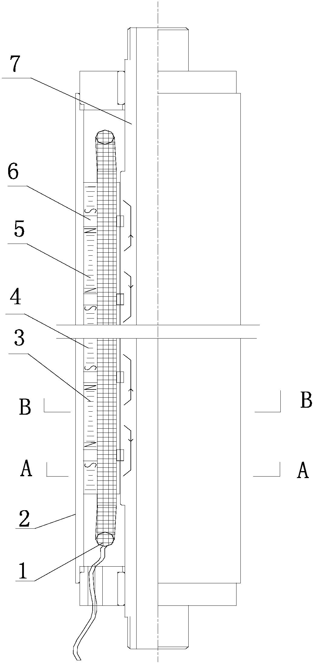
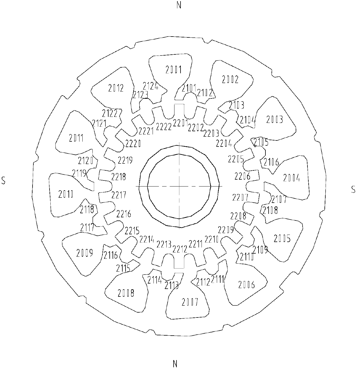
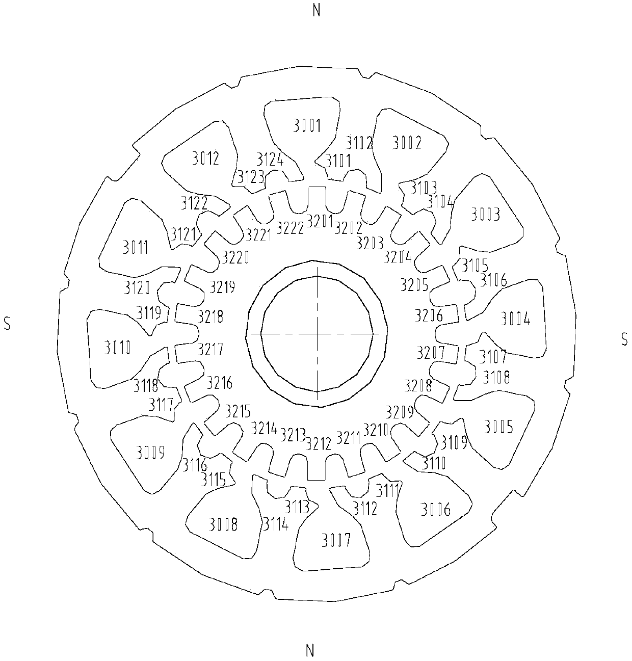
[0032] Such as figure 1 The present invention shown is an axial excitation low-speed synchronous motor with an axial through-tooth integral rotor, such as Figure 8 As shown, the segmented stator core 3 of the S polarity segment and the segmented stator core 4 of the N polarity segment are respectively shifted from the large and small teeth in the circumferential direction of the slots, such as Figure 9 As shown, the stator core punching sheet 5 is stacked, the S polarity segment stator core 3, the N polarity segment stator core 4, and the annular excitation coil 6 are coaxial in sequence in an axial forward and reverse manner. Installed and fixed in the casing 2, such as Figure 10 , Figure 11 As shown, the axial through-tooth integral hollow rotor 7 is coaxially installed in the inner cavity of the segmented stator core 3 of the S polarity segment and the segmented stator core 4 of the N polarity segment. An electromagnetic air gap of 0.2 mm is left on the surface of th...


PUM


Abstract

The present invention relates to an axial excitation low-speed synchronous motor with an axial straight-through tooth integral rotor. An S-polarity segment sectionalized stator core 3 and N-polarity segment sectionalized stator core 4 are separately formed by stacking large and small tooth circumferential offset tooth slot stator core punched sheets 5; the S-polarity segment sectionalized stator core 3, the N-polarity segment sectionalized stator core 4 and an annular excitation coil 6 are axially mounted in a case 2 co-axially and sequentially in a forward direction and reverse direction alternate manner; an axial through tooth overall hollow rotor 7 is coaxially mounted in the inner cavities of the S-polarity segment sectionalized stator core 3 and the N-polarity segment sectionalized stator core 4; and 0.2-mm electromagnetic air gaps are left between the axial through tooth overall hollow rotor 7 and the S-polarity segment sectionalized stator core 3 and the N-polarity segment sectionalized stator core 4.

Description

technical field [0001] The invention relates to an axial excitation low-speed synchronous motor with an axial through-tooth integral rotor. Background technique [0002] The existing axial excitation low-speed motor technology is: the stator of the commonly used axial excitation synchronous low-speed motor is made of silicon steel sheets as the general synchronous motor. Phase AC windings to generate a rotating magnetic field. The rotor structure is generally adopted. A section of axially magnetized permanent magnet steel is arranged in the middle of the rotor. The two ends of the magnet steel are equipped with magnetic yokes made of magnetically conductive materials, and the surface of the yoke has open grooves. Two adjacent rotor yokes are staggered by half a tooth pitch in the circumferential direction. There are also axial excitation elements with ring-shaped excitation coils or permanent magnets placed between the stator segments. Although the rotor adopts an integral ...

Claims


Application Information

Patent Timeline
Patent Type & Authority Applications(China)
IPC IPC(8): H02K21/24H02K1/14H02K1/17H02K1/22
Inventor 许泽生许中昕
Owner 哈尔滨森特能源科技有限公司
Why Eureka
Try Eureka