Charging and discharging robot for toothbrush production assembly line

A production line, loading and unloading technology, applied in the field of loading and unloading manipulators, can solve the problems of unsuitability for popularization, high operation and maintenance costs, high production equipment purchase costs, etc. Effect

Inactive Publication Date: 2018-01-26
SHAANXI LAIFU TECH DEV CO LTD
View PDF0 Cites 2 Cited by
  • Summary
  • Abstract
  • Description
  • Claims
  • Application Information

AI Technical Summary

Problems solved by technology

Among them, the handle injection molding stage, the brush head hair planting processing stage, and the product packaging stage all require manual loading and unloading auxiliary operations, and manual loading and unloading is quite unfavorable for improving production efficiency and saving manpower operation and maintenance costs. For this reason, some manufacturers The introduction of automated assembly line production equipment to improve, however, the purchase cost of automated assembly line production equipment is high, and some auxiliary mechanisms that use negative pressure systems to realize loading and unloading have high operation and maintenance costs, and are not suitable for popularization

Method used


Image

  • Charging and discharging robot for toothbrush production assembly line
  • Charging and discharging robot for toothbrush production assembly line
  • Charging and discharging robot for toothbrush production assembly line

Examples


Embodiment Construction

[0023] Attached below Figure 1-7 An embodiment of the present invention is described.

[0024] The following examples facilitate a better understanding of the present invention, but do not limit the present invention. The implementation of the control circuit in the following embodiments is a conventional control method unless otherwise specified. The components used in the following examples are commercially available unless otherwise specified.

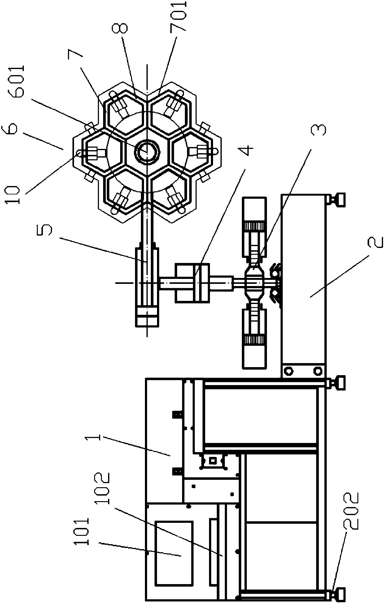
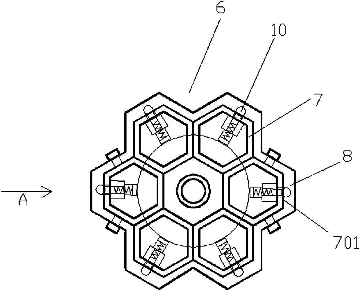
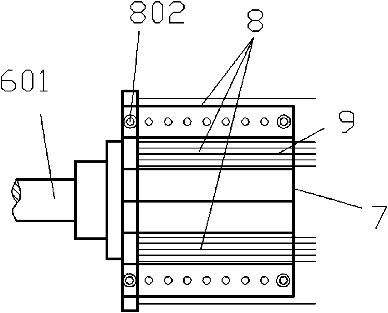
[0025] Robots used for loading and unloading materials in the toothbrush production line, (such as figure 1 As shown) has a PLC control cabinet 1, a working platform 2 is installed on one side of the PLC control cabinet 1, and the working platform 2 is a box-type structure. The upper end of the working platform 2 is equipped with a column rotary cylinder 3, and the column rotary cylinder 3 The free end is connected to the lifting cylinder 4, and the lifting free end of the lifting cylinder 4 is connected to the telescopic cylind...


PUM

PropertyMeasurementUnit
thicknessaaaaaaaaaa

Abstract

The invention provides a charging and discharging robot for a toothbrush production assembly line. The charging and discharging robot is provided with a PLC control cabinet and a working platform. Theworking platform is sequentially provided with stand column rotation air cylinders, a stand column lifting air cylinder and a stand column horizontal telescopic air cylinder. An intermittent rotationmechanism intermittently rotating by a certain acute angle is connected with the free end of the telescopic air cylinder. The intermittent rotation mechanism is provided with a polyhedral charging mold which rotates along with a rotary shaft coaxially and synchronously and is provided with a plurality of concentric charging end faces of the same structure. A replaceable material clamping templatemade from polyurethane is fixedly mounted on each charging end face of the polyhedral charging mold in a matched mode. The material clamping templates are integrally formed and provided with a plurality of clamping grooves connected with brush holders in a clamped mode. Spring material pushing balls used for pushing the brush holders away are mounted at the bottom ends of all the material clamping templates. The mold production cycle is short, the machining cost is low, realization is easy, the later operation and maintenance cost is low, the production progress of the assembly line can be accelerated on the basis that the cost is controlled, the multiple-degree-of-freedom intermittent rotary batch charging and discharging functions are achieved, the labor cost is reduced, the charging and discharging robot is more economical, convenient and practical, and the economic benefits of enterprises are increased.

Description

technical field [0001] The invention belongs to the technical field of loading and unloading manipulators, and in particular relates to a robot for loading and unloading materials in a toothbrush production line. Background technique [0002] At present, the toothbrush production line includes several stages of mold development, handle injection molding, brush head hair planting processing, hair cutting and grinding processing, and product post-packaging. Among them, the handle injection molding stage, the brush head hair planting processing stage, and the product packaging stage all require manual loading and unloading auxiliary operations, and manual loading and unloading is quite unfavorable for improving production efficiency and saving manpower operation and maintenance costs. For this reason, some manufacturers Introduce automatic assembly line production equipment to improve. However, the purchase cost of automatic assembly line production equipment is high, and some ...

Claims


Application Information

Patent Timeline
Patent Type & Authority Applications(China)
IPC IPC(8): B29C45/18B29C45/42
Inventor 杨晓东
Owner SHAANXI LAIFU TECH DEV CO LTD
Why Eureka
Try Eureka