Negative-pressure liquefied gas preparation process

A technology of liquefied gas and preparation technology, which is applied to equipment discharged from pressure vessels, pressure vessels, mechanical equipment, etc., which can solve problems such as energy consumption, low mixing efficiency of air and oil, and increased equipment complexity, etc., to achieve reduction Volume, reduce energy consumption, improve the effect of preparation efficiency

Inactive Publication Date: 2018-01-26
SHANDONG UNIV OF TECH
View PDF8 Cites 0 Cited by
  • Summary
  • Abstract
  • Description
  • Claims
  • Application Information

AI Technical Summary

Problems solved by technology

[0003] However, no matter how the equipment and process of the existing paint-making process change, it is always impossible to get rid of the basic form of "gas is blown into the oil, the gas and the oil are naturally mixed, and then the air is mixed with the gas".
This form has been continuously improved in technology and equipment to produce stable gas, but the mixing efficiency of air and oil is low; or to increase the complexity of the equipment and / or energy consumption in order to improve the mixing efficiency

Method used


Image

  • Negative-pressure liquefied gas preparation process

Examples


Embodiment 1

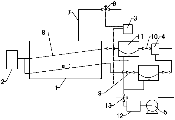
[0025] Holes with a diameter of 1.0mm are evenly distributed on the oil-gas mixing tube 8, and the density of the holes on the oil-gas mixing tube 8 is 3 pcs / cm 2 The wall thickness of the oil-gas mixing tube 8 is 2.5mm; the oil-gas mixing tube 8 is inclined upward from the air inlet end to the other end, and the inclination angle a between the oil-gas mixing tube 8 and the horizontal plane is 10°;

[0026]After the vacuum pump 5 is turned on, the negative pressure buffer box 12 forms a negative pressure. The controller 3 controls each negative pressure pipe electromagnetic valve 13 to open at a certain time interval. The gas is extracted alternately, the space is reduced, and the space in each gas chamber becomes larger, the pressure decreases, the front check valve 9 is opened, and a negative pressure airflow is formed in the oil-gas mixing pipe 8, and air is sucked into the air filter 2 At the same time, the holes on the oil-gas mixing tube 8 suck in liquid light hydrocarbo...

Embodiment 2

[0028] Holes with a diameter of 0.8 mm are evenly distributed on the oil-gas mixing tube 8, and the density of the holes on the oil-gas mixing tube 8 is 4 pcs / cm 2 The wall thickness of the oil-gas mixing tube 8 is 3mm; the oil-gas mixing tube 8 is inclined upward from the inlet end to the other end, and the inclination angle a between the oil-gas mixing tube 8 and the horizontal plane is 12°;

[0029] After the vacuum pump 5 is turned on, the negative pressure buffer box 12 forms a negative pressure. The controller 3 controls each negative pressure pipe electromagnetic valve 13 to open at a certain time interval. The gas is extracted alternately, the space is reduced, and the space in each gas chamber becomes larger, the pressure decreases, the front check valve 9 is opened, and a negative pressure airflow is formed in the oil-gas mixing pipe 8, and air is sucked into the air filter 2 At the same time, the holes on the oil-gas mixing tube 8 suck in liquid light hydrocarbons a...

Embodiment 3

[0031] Holes with a diameter of 0.5 mm are evenly distributed on the oil-gas mixing tube 8, and the density of the holes on the oil-gas mixing tube 8 is 5 pcs / cm 2 The wall thickness of the oil-gas mixing tube 8 is 2 mm; the oil-gas mixing tube 8 is inclined upward from the inlet end to the other end, and the inclination angle a between the oil-gas mixing tube 8 and the horizontal plane is 10°;

[0032] After the vacuum pump 5 is turned on, the negative pressure buffer box 12 forms a negative pressure. The controller 3 controls each negative pressure pipe electromagnetic valve 13 to open at a certain time interval. The gas is extracted alternately, the space is reduced, and the space in each gas chamber becomes larger, the pressure decreases, the front check valve 9 is opened, and a negative pressure airflow is formed in the oil-gas mixing pipe 8, and air is sucked into the air filter 2 At the same time, the holes on the oil-gas mixing tube 8 suck in liquid light hydrocarbons ...


PUM

PropertyMeasurementUnit
Thicknessaaaaaaaaaa

Abstract

The invention provides a negative-pressure liquefied gas preparation process and belongs to the technical field of liquefied gas preparation. The negative-pressure liquefied gas preparation process ischaracterized in that after a vacuum pump (5) is opened, negative pressure is formed in an oil-gas mixing pipe (8), air is sucked in, meanwhile liquid light hydrocarbons in a constant-liquid-level oil storage tank (1) are sucked into holes in the oil-gas mixing pipe (8), and the liquid light hydrocarbons in the oil-gas mixing pipe (8) are mixed with the air and gasified into air-mixed gas and enters gas chambers of negative-pressure tanks (11); and after the liquid light hydrocarbons in the constant-level oil liquid tank (1) are reduced, the liquid light hydrocarbons are supplemented in realtime so that the center position of the oil-gas mixing pipe (8) can be always in the position 45 cm-55 cm below the liquid light hydrocarbon liquid level. According to the negative-pressure liquefiedgas preparation process, because gasification can be accelerated under both the negative pressure and the air flow, the light hydrocarbons are gasified quickly in the flowing process, the size of thesystem is reduced, the energy consumption is lowered, and the gas preparation efficiency is improved.

Description

technical field [0001] A negative pressure liquefied gas preparation process belongs to the technical field of liquefied gas preparation. Background technique [0002] The light hydrocarbon gas generation system uses liquid light hydrocarbons (mainly composed of C5) as raw materials, and converts liquid light hydrocarbons into air-mixed gas through special gasification equipment, so as to improve combustion efficiency and realize full utilization of existing energy. The existing fuel gas generating device is basically a bubbling type, that is, the air is blown into the gas generating tank, and when the bubbles rise in the oil, the oil contacts the bubbles, and the oil molecules enter the bubbles to form a combustible air-mixed light hydrocarbon gas. In order to ensure the quality (calorific value) of fuel gas, the common method is to increase the contact area between gas and oil and increase the residence time of bubbles in the oil, and cooperate with auxiliary heating to a...

Claims


Application Information

Patent Timeline
IPC IPC(8): F17C7/04F17C13/00F17C13/02F17C13/04F17D3/01
Inventor 万隆巴奉丽刘国柱
Owner SHANDONG UNIV OF TECH
Why Eureka
Try Eureka