Space-ray-tracing-based method for designing secondary mirror hood and square-tapered extinction cone

A technology of ray tracing and design method, which is applied in the field of aerospace remote sensing, can solve problems such as occlusion, and achieve the effects of volume reduction, size minimization, and weight reduction

Active Publication Date: 2018-01-30
BEIJING RES INST OF SPATIAL MECHANICAL & ELECTRICAL TECH
View PDF4 Cites 4 Cited by
  • Summary
  • Abstract
  • Description
  • Claims
  • Application Information

AI Technical Summary

Problems solved by technology

However, there are two problems in the traditional two-dimensional projection design method: first, the traditional design is only for the diagonal field of view, and does not correspond to the real field of view of the optical system, so the size of the secondary mirror hood will be larger than the actual The required size introduces unnecessary occlusion; second, the traditional design requires an extraordinary primary mirror hood to cooperate with the secondary mirror hood, and when the length of the primary mirror hood is limited, an oversized secondary mirror shading is required cover to match

Method used


Image

  • Space-ray-tracing-based method for designing secondary mirror hood and square-tapered extinction cone
  • Space-ray-tracing-based method for designing secondary mirror hood and square-tapered extinction cone
  • Space-ray-tracing-based method for designing secondary mirror hood and square-tapered extinction cone

Examples


Embodiment Construction

[0058] For the visible spectrum, the field of view in the X direction is ±1.0°, the field of view in the Y direction is -1~-0.6°, and the RC system with an entrance pupil diameter of 359.6mm is used for the extinction cone of the secondary mirror hood and the central hole of the square conical primary mirror. Joint design.

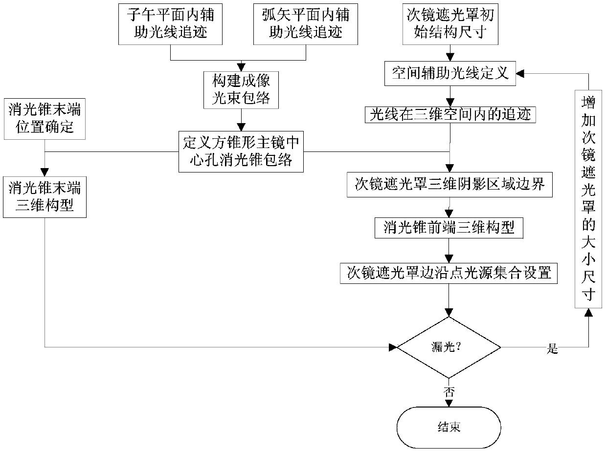
[0059] Such as figure 1 Shown, concrete steps of the present invention are as follows:

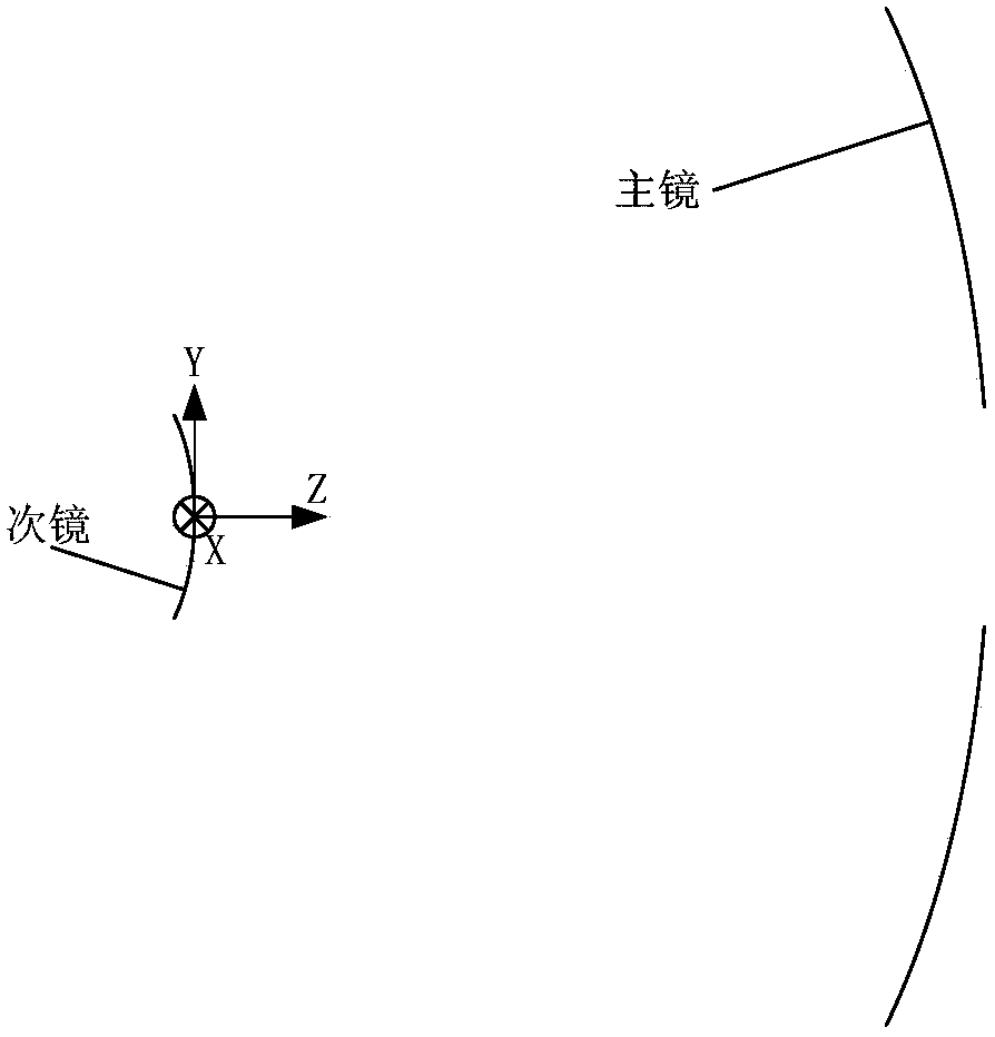
[0060] (1) According to figure 2 As shown, a Cartesian rectangular coordinate system is established;

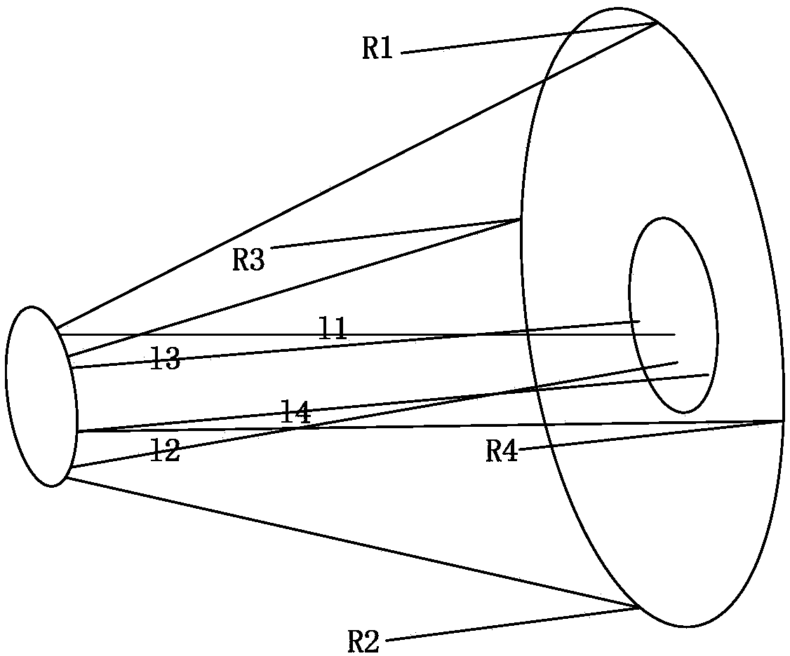
[0061] (2) Based on the tracing results of the four auxiliary rays in the meridional and sagittal planes, the boundary of the extinction cone of the central hole of the square conical primary mirror is calculated

[0062] build as image 3 The equations of the four auxiliary rays R1, R2, R3 and R4 shown are:

[0063]

[0064]

[0065]

[0066]

[0067] Tracing the 4 auxiliary rays in Fred, the linear equations l1', l2', l3' and l4' of the 4 rays refl...


PUM


Abstract

The invention relates to a space-ray-tracing-based method for designing a secondary mirror hood and a square-tapered extinction cone. The method comprises: step one, establishing a Cartesian rectangular coordinate system used during a design process; step two, establishing auxiliary light in a meridian plane and a sagittal surface and carrying out calculation to obtain a boundary of a square-tapered main mirror central-hole extinction cone; step three, determining the position and configuration of the tail end of the square-tapered main mirror central-hole extinction cone; step four, definingan initial structure of a secondary mirror hood; step five, constructing a spatial auxiliary ray and carrying out calculation to obtain the position and configuration of the front end of a square-tapered extinction cone; step six, setting a point light source set at the edge of a conical surface, carrying out ray tracing, carrying out statistics of light source numbers with light leakage possibility, and increasing the size of the conical surface correspondingly; step seven, determining final spatial positions and three-dimensional configuration of the tail end and the front end of the square-tapered main mirror central-hole extinction cone; and step eight, carrying out calculation to obtain three-dimensional configuration of the secondary mirror hood.

Description

technical field [0001] The invention relates to a design method for a secondary mirror hood and a square-cone extinction cone based on space ray tracing, and is suitable for secondary mirror hoods and squares of various coaxial reflection systems or systems with coaxial reflection systems as the main optics. The design of the extinction cone of the central hole of the conical primary mirror belongs to the technical field of aerospace remote sensing. Background technique [0002] The stray light suppression structure design of the optical system of aerospace remote sensors is an indispensable and important link in the development and production process, and the outer shading cover of the primary mirror, the shading cover of the secondary mirror and the extinction cone of the central hole of the primary mirror are all kinds of coaxial reflection systems or The most important and most commonly used stray light suppression structure for various types of coaxial reflection system...

Claims


Application Information

Patent Timeline
Patent Type & Authority Applications(China)
IPC IPC(8): G02B27/00
Inventor 张庭成阮宁娟李洋邢辉焦文春廖志波李可
Owner BEIJING RES INST OF SPATIAL MECHANICAL & ELECTRICAL TECH
Why Eureka
Try Eureka