
Beam expanding and real-time focusing device based on CO2 laser tube light source

A laser beam and laser tube technology, applied in the laser field, can solve the problems of large spot, difficult foreign matter removal, large laser divergence angle, etc., and achieve the effect of small spot, strong cleaning ability and high laser power density

Inactive Publication Date: 2018-01-30
BEIJING INST OF ELECTRONICS SYST ENG
View PDF5 Cites 1 Cited by
  • Summary
  • Abstract
  • Description
  • Claims
  • Application Information

AI Technical Summary

Problems solved by technology

Collimated beam emission method, CO 2 The CO output from the laser tube 2 The laser divergence angle is large, the spot on the target is large, and the laser power density is low. It is difficult to directly remove foreign objects on long-distance wires, and the utilization rate of laser power is low.
However, in the focused transmission mode with a fixed focal length, the beam expander optical system adopts the same focal length, which cannot achieve CO 2 The laser focuses on targets at different distances, making it difficult to remove foreign objects at different distances

Method used


Image

  • Beam expanding and real-time focusing device based on CO2 laser tube light source

Examples


Embodiment Construction

[0018] The present invention is described in detail by the following examples. It is necessary to point out that this example is only used to further illustrate the present invention, and can not be interpreted as limiting the protection scope of the present invention. Those skilled in the art can according to the above invention Some non-essential improvements and adjustments have been made to the content. In the case of no conflict, the embodiments and the features in the embodiments of the present invention can be combined with each other.

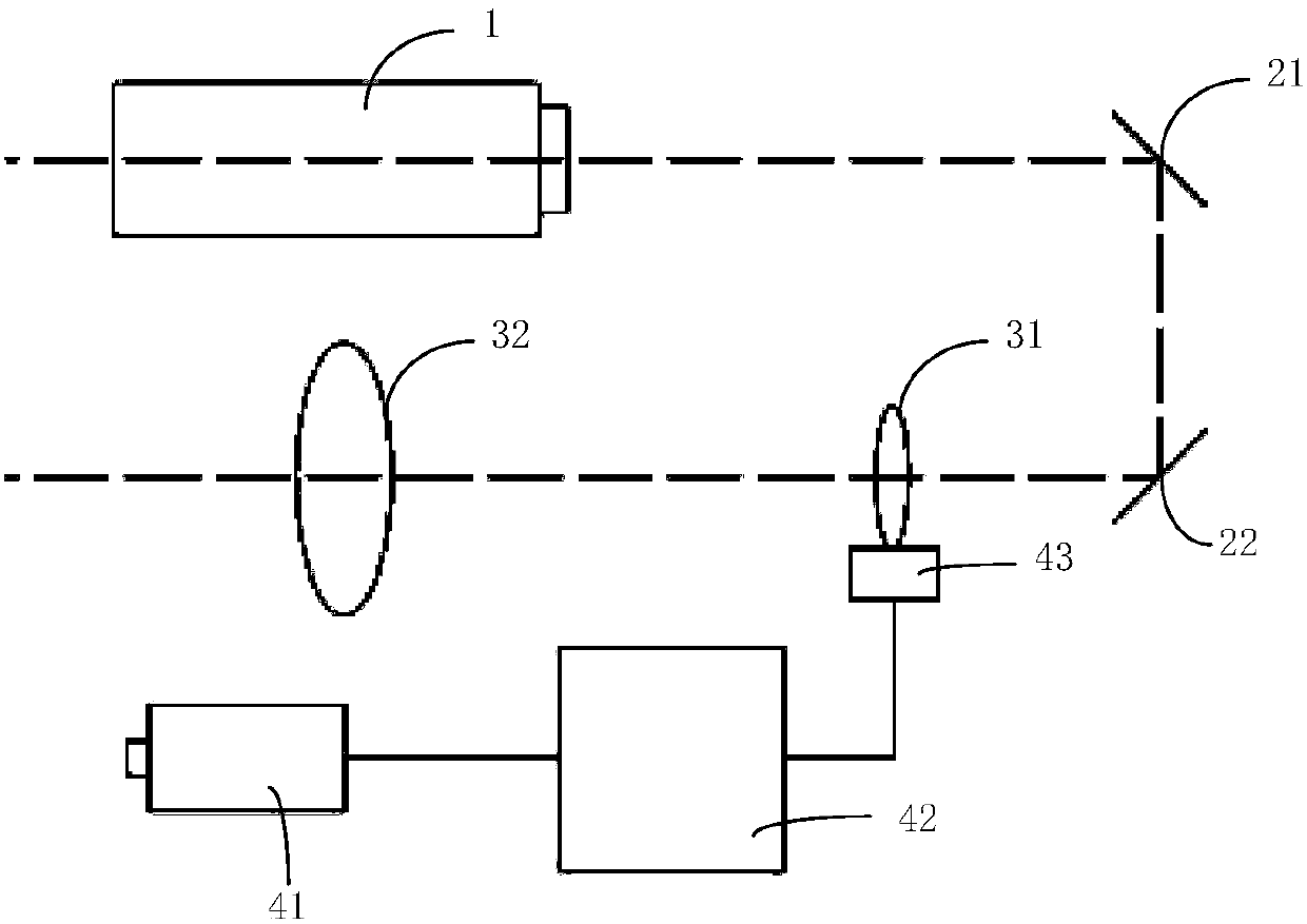
[0019] Such as figure 1 As shown, the present invention provides a preferred embodiment, a CO-based 2 Beam expansion and real-time focusing device of laser tube light source, including: CO 2 Laser tube 1, CO 2 Laser beam expander unit and CO 2 Laser focusing unit;

[0020] The CO 2 Laser tube 1 is used to generate CO 2 Laser beam; remove foreign matter on the wire after focusing and beam expansion;

[0021] The CO 2 The laser b...


PUM


Abstract

The invention discloses a beam expanding and real-time focusing device based on a CO2 laser tube light source. Two 45-degree plane mirrors are utilized to turn an optical axis direction of a CO2 laserbeam by 180 degrees, thereby shortening a laser emission cylinder, realizing miniaturization and portability of the laser emission cylinder, and facilitating field transportation and work; and real-time focusing can be performed according to the distance of a target, thereby achieving the effects that for targets of different distances, under the condition of constant laser tube power, CO2 laserspots are the smallest, laser power density is the highest, and a capability of clearing foreign matter is the highest.

Description

technical field [0001] The invention relates to the field of laser technology, in particular to a CO-based 2 Beam expansion and real-time focusing device of laser tube light source. Background technique [0002] The power lines of the transmission network are usually exposed and have no insulation layer, and foreign objects such as kites, cloth strips, and plastic sheets hanging on them should be disposed of in time. Otherwise, if it is contaminated with rain, snow, dew or affected by other conditions, it will easily cause phase-to-phase short circuit, and there will be safety hazards such as fire. In addition, it may cause tripping, endangering the power supply in large areas of urban areas and causing great economic losses. The general methods for cleaning foreign matter on the power line include: manually climbing up the pole tower for cleaning, lifting the insulated arm truck to pick it up, and unmanned aerial vehicle spraying fire to clean it up, etc. Climbing up the ...

Claims


Application Information

Patent Timeline
Patent Type & Authority Applications(China)
IPC IPC(8): G02B27/09H01S3/00
Inventor 周洁于道林李岩杨静琦马喆姜来周恒妍
Owner BEIJING INST OF ELECTRONICS SYST ENG
Learn More