
Chain type cement mixing pile machine

A cement mixing pile and chain technology, which is applied in the field of cement mixing piles, can solve the problems of affecting operation efficiency, cumbersome assembly, difficult handling, etc., and achieve the effects of saving transportation costs, facilitating transportation or storage, and facilitating transportation.

Active Publication Date: 2018-02-02
JIANGSU JIANYUAN CONSTR CO LTD
View PDF5 Cites 0 Cited by
  • Summary
  • Abstract
  • Description
  • Claims
  • Application Information

AI Technical Summary

Problems solved by technology

[0002] Cement mixing pile is one of the commonly used equipment in construction at present. It is used to build the foundation for the building. The cement is mixed with the soft soil in the ground soil layer to form a solid pile through the cement mixing method. Cement mixing piles are driven through processes such as drilling, mixing, high-pressure grouting, and lifting; in order to ensure the stability of the building, deep piles need to be driven into the ground, and longer drill pipes are required at this time, so the volume of traditional cement mixing piles It is large, cumbersome to assemble, and difficult to transport. During the operation, a high bracket is required to fix the drill pipe. It needs to be equipped with a very powerful motor to drive the rotation. At the same time, the cement slurry needs to be lifted more than ten meters before being sprayed into the ground pile. It causes a great waste of energy and seriously affects the operation efficiency; in addition, there are safety risks such as drill pipe falling off and workers being injured

Method used


Image

  • Chain type cement mixing pile machine
  • Chain type cement mixing pile machine
  • Chain type cement mixing pile machine

Examples


Embodiment

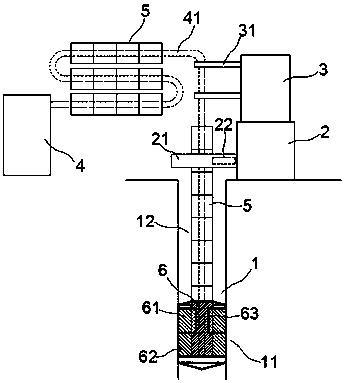
[0023] exist Figure 1 to Figure 3 In the shown embodiment, the chain cement mixing pile driver includes a drill pipe 1, a driving machine 2, a bearing frame 3 and a grouting machine 4;

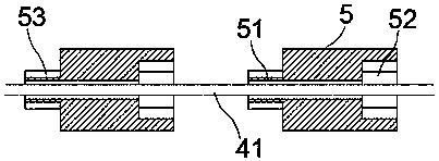
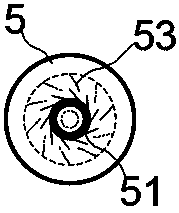
[0024] The drill pipe 1 includes a drill bit 11 and a rod body 12, the drill bit 11 is detachably mounted on the end of the rod body 12; a spray port is provided at the bottom of the drill bit 11; the rod body 12 is assembled from the transmission column 5 head to tail, The upper end of the transmission column 5 is provided with a transmission head 51, and the lower end is provided with a transmission groove 52 matched with the transmission head 51, and the transmission head 51 and the transmission groove 52 are provided with matching transmission teeth 53; the transmission head 51 and the transmission groove The transmission tooth 53 on the 52 is a ratchet tooth, and the transmission head 51 and the transmission groove 52 rotate synchronously in the clockwise direction, and rotate relatively...


PUM


Abstract

The invention relates to a chain type cement mixing pile machine which comprises a drill rod, a driver, a bearing frame and a grouting machine. The drill rod comprises a drill bit and a rod body, therod body is formed by splicing transmission columns end to end, the transmission columns are provided with transmission holes in the axis, a bearing pipe is sleeved with the transmission columns in series, and the transmission columns can freely slide on the bearing pipe. One end of the bearing pipe is connected with the drill bit, the other end of the bearing pipe is connected to the grouting machine, the outer column faces of the transmission columns are provided with driving teeth, the driving teeth are engaged with an upper driving wheel on the driver, the driving teeth can be moved relative to the driving wheel in the axial direction of the transmission columns, the bearing frame comprises a lifting arm matched with the bearing pipe, and the bearing pipe can be moved up and down underpulling of the lifting arm. According to the chain type cement mixing pile machine, the structure is novel and unique, conveying and assembling are convenient, operation efficiency is effectively improved, construction occupied space is small, use is safe and efficient and saves energy, and grouting efficiency is improved.

Description

technical field [0001] The invention relates to a building construction equipment, in particular to a cement mixing pile. Background technique [0002] Cement mixing pile is one of the commonly used equipment in construction at present. It is used to build the foundation for the building. The cement is mixed with the soft soil in the ground soil layer to form a solid pile through the cement mixing method. Cement mixing piles are driven through processes such as drilling, mixing, high-pressure grouting, and lifting; in order to ensure the stability of the building, deep piles need to be driven into the ground, and longer drill pipes are required at this time, so the volume of traditional cement mixing piles It is large, cumbersome to assemble, and difficult to transport. During the operation, a high bracket is required to fix the drill pipe. It needs to be equipped with a very powerful motor to drive the rotation. At the same time, the cement slurry needs to be lifted more th...

Claims


Application Information

Patent Timeline
Patent Type & Authority Applications(China)
IPC IPC(8): E02D5/46E21B3/02
CPCE02D5/46E02D2250/003E02D2250/0038E21B3/02
Inventor 钱娟娟
Owner JIANGSU JIANYUAN CONSTR CO LTD
Learn More