Dielectric nano-brick array structure and application thereof as high-reflection film and high-permeability film

An array structure and dielectric technology, applied in the field of applied optics, can solve the problems of complex production process, scarce coating materials, scarce resources, etc., and achieve the effect of simple and mature technology and flexible design method.

Inactive Publication Date: 2018-02-06
WUHAN UNIV
View PDF4 Cites 15 Cited by
  • Summary
  • Abstract
  • Description
  • Claims
  • Application Information

AI Technical Summary

Problems solved by technology

For the high-transparency film, due to the limitation of the refractive index of the material, the coating material is relatively rare. Magnesium fluoride is the best preparation material, but there are disadvantages such as scarce resources and high cost.
[0003] The traditional use of optically transparent dielectric films to produce high-transparency and high-reflection films has the following problems: (1) The manufacturing process is complicated; (2) The high-transparency and high-reflection films produced have low bandwidth in the working optical band; (3) Coating Material resources are scarce and raw material costs are high
High-transparency films and high-reflection films have great application prospects in the field of applied optics, but the above problems limit their application, so the industry urgently needs new technology updates and revolutions

Method used


Image

  • Dielectric nano-brick array structure and application thereof as high-reflection film and high-permeability film
  • Dielectric nano-brick array structure and application thereof as high-reflection film and high-permeability film
  • Dielectric nano-brick array structure and application thereof as high-reflection film and high-permeability film

Examples


Embodiment Construction

[0035] In order to more clearly illustrate the embodiments of the present invention and / or the technical solutions in the prior art, the specific implementation manners of the present invention will be described below with reference to the accompanying drawings. Obviously, the drawings in the following description are only embodiments of the present invention, and those skilled in the art can also obtain other drawings based on these drawings and obtain other implementation.

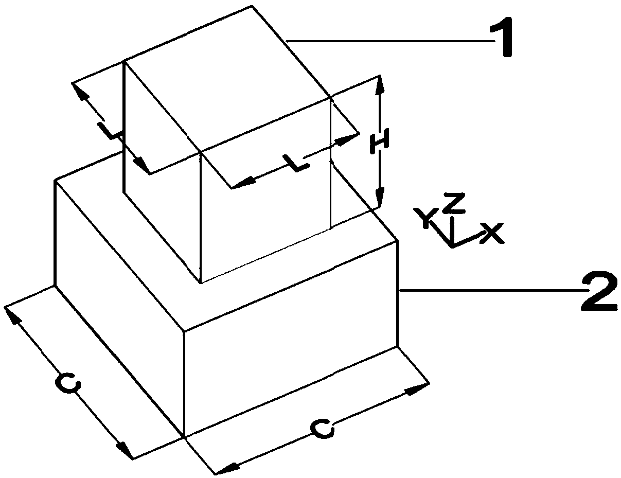
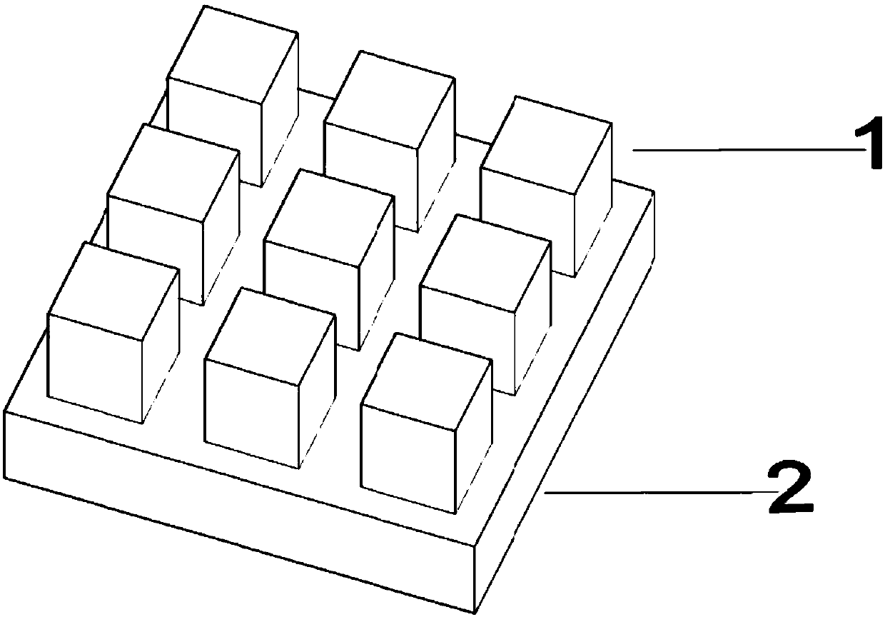
[0036] See Figure 1~2 The dielectric nanobrick array structure shown includes two layers, from bottom to top, the dielectric nanobrick array 1 and the substrate 2, wherein the dielectric nanobrick array 1 is composed of dielectric nanobricks arranged periodically, and the dielectric nanobricks are long and wide Equal regular quadrangular prisms, and their length, width and height are all sub-wavelength dimensions. For the structure of a single dielectric nanobrick unit see figure 1 . In this embodim...


PUM


Abstract

The invention discloses a dielectric nano-brick array structure and the application thereof as a high-reflection film and a high-permeability film. The dielectric nano-brick array structure comprisesa substrate and a dielectric nano-brick array on the substrate. The dielectric nano-brick array is formed by periodically arranging dielectric nano-bricks and the dielectric nano-bricks are in a regular quadrangular prism shape. The bottom surfaces of the dielectric nano-bricks are square, wherein the length, the width and the height of the dielectric nano-bricks are sized in sub-wavelength scale.When the dielectric nano-brick array structure is used as a high-reflectivity film, the structural parameters of the dielectric nano-brick array structure are optimized. In this way, the Mie resonance can be generated when the s-wave and the p-wave are incident at a working wavelength. When the dielectric nano-brick array structure is used as a high-permeability film, the structural parameters ofthe dielectric nanometer brick array structure are optimized. In this way, the equivalent refractive index of a mixed layer is between the refractive index of a medium around the mixed layer and therefractive index of the substrate. According to the technical scheme of the invention, the high-reflection film and the high-permeability film, based on the dielectric nano-brick array structure, arehigh in working efficiency in the whole communication wave band.

Description

technical field [0001] The invention belongs to the field of applied optics, in particular to a dielectric nano-brick array structure and its application as a high reflection film and a high transmission film. Background technique [0002] At present, anti-reflection coatings and anti-reflection coatings are mainly made of optically transparent dielectric films, that is, using physical and chemical methods to coat transparent dielectric films on the smooth surface of glass or metal, using the reflection, refraction and Superposition to achieve antireflection or antireflection. According to the needs, the high-permeability film and the high-reflection film are generally divided into single-dielectric film, double-dielectric film or multi-dielectric film. The effect of the multi-media film type high-permeability film and high-reflection film is relatively good, and it is usually prepared by materials such as magnesium fluoride, titanium oxide, lead sulfide, and lead selenide....

Claims


Application Information

Patent Timeline
Patent Type & Authority Applications(China)
IPC IPC(8): G02B1/00G02B1/10G02B1/118
CPCG02B1/002G02B1/10G02B1/118
Inventor 郑国兴戴琦李子乐邓联贵邓娟刘勇毛庆洲何平安李松
Owner WUHAN UNIV
Why Eureka
Try Eureka