High-efficiency flat wire generator rectifier structure and assembling method thereof
A generator and rectifier technology, applied in the manufacture of motor generators, electromechanical devices, structural connections, etc., can solve problems such as temperature conduction, poor radiation, rectifier failure, etc., achieve uniform temperature gradient, reduce shaking space, improve power and The effect of product reliability
- Summary
- Abstract
- Description
- Claims
- Application Information
AI Technical Summary
Problems solved by technology
Method used
Image

Examples
Embodiment Construction
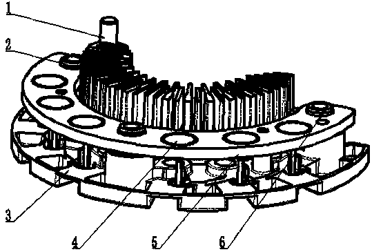
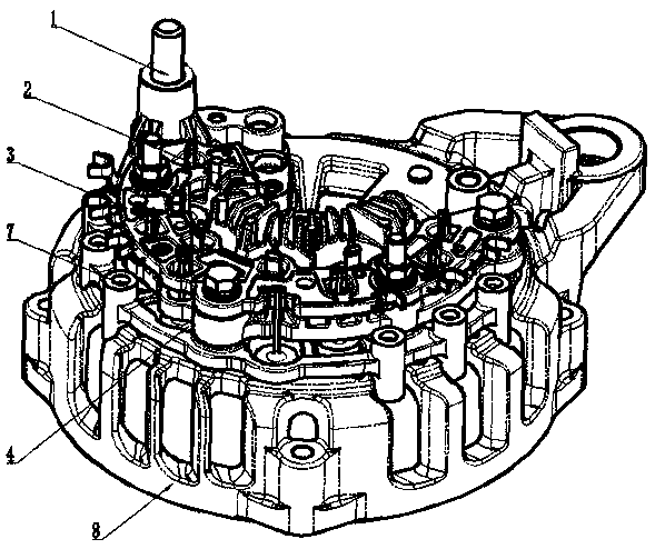
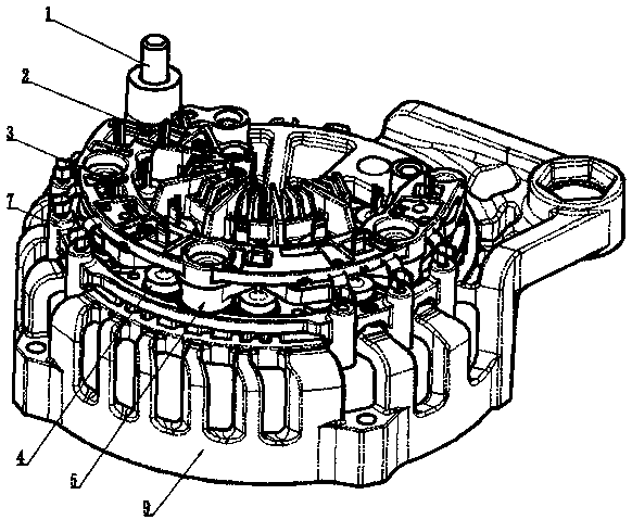
[0049] Such as Figure 4 , Figure 5 , Figure 6 , Figure 7 , Figure 8 and Figure 9 As shown: the present invention includes a conductive negative plate 5, an intermediate support insulating bracket 7, a conductive positive plate 2, a bus bridge support 3, a positive output screw 1, a rectifier diode 4, a tubular rivet 16, a rear fixing cover 9 for the generator, and a The fixed cover supports the boss 12 and the plastic protective cover 10 . The rectifier diode 4 converts alternating current into direct current, the conductive negative plate 5 and the conductive positive plate 2 play the role of fixing the rectifying diode, conduction and heat dissipation, the bus bridge bracket 3 is connected to the stator wire for confluence, the positive output screw 1 outputs current to the outside, and the rear cover of the generator The supporting boss 12 supports and fixes the rectifier, and the plastic protective cover 10 protects the rectifier and adjusts the generator air du...
PUM
| Property | Measurement | Unit |
|---|---|---|
| Height | aaaaa | aaaaa |
Abstract
Description
Claims
Application Information