Wilkinson power divider

A power divider and metal technology, which can be applied to waveguide-type devices, circuits, connecting devices, etc., can solve the problems of large circuit area of ​​ultra-wideband Wilkinson power dividers.

Active Publication Date: 2018-02-09
青岛君戎华讯太赫兹科技有限公司
View PDF5 Cites 2 Cited by
  • Summary
  • Abstract
  • Description
  • Claims
  • Application Information

AI Technical Summary

Problems solved by technology

[0004] Based on this, it is necessary to provide a Wilkinson power divider for t

Method used


Image

  • Wilkinson power divider
  • Wilkinson power divider
  • Wilkinson power divider

Examples


Embodiment Construction

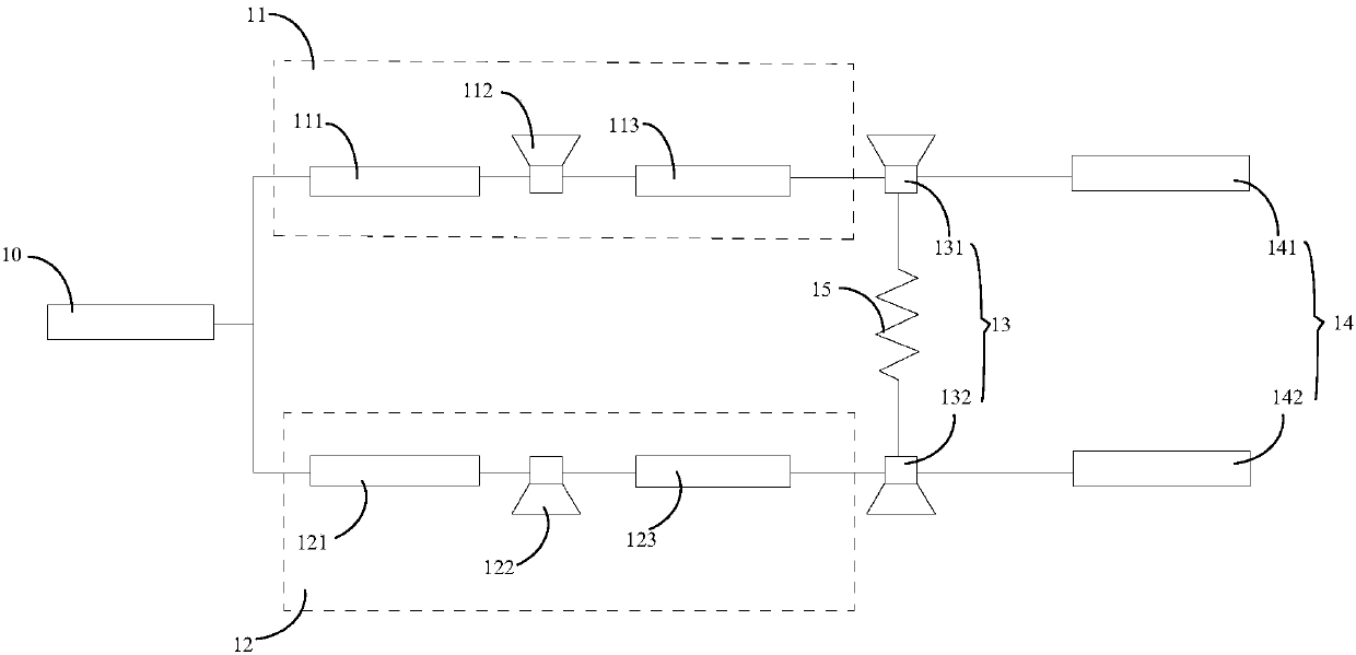
[0028] see figure 1 , figure 1 It is a structural schematic diagram of a Wilkinson power divider in an embodiment.

[0029] At present, the academic and industrial circles are generally more concerned about the commercial application value of the 3.1GHz-10.6GHz ultra-wideband system. Therefore, in this embodiment, the Wilkinson power divider broadens the frequency band to a range of 3.1 GHz-10.6 GHz.

[0030] In this embodiment, the Wilkinson power divider includes a dielectric layer, a signal metal layer attached to one side of the dielectric layer, and a metal bottom layer attached to the other side of the dielectric layer, the signal metal layer, the dielectric layer Layer and metal bottom layer form a microstrip line structure, and the signal metal layer includes an input port 10, a first microwave transmission branch 11, a second microwave transmission branch 12, a second triangular pile structure 13, an output port 14 and an isolation resistor 15 .

[0031] The input...


PUM

PropertyMeasurementUnit
Impedanceaaaaaaaaaa
Electrical lengthaaaaaaaaaa

Abstract

The invention discloses a wilkinson power divider, which comprises a dielectric layer, a signal metal layer attached to one side of the dielectric layer and a metal bottom layer attached to the otherside of the dielectric layer, wherein the signal meta layer, the dielectric layer and the metal bottom layer form a microstrip structure; and the signal metal layer comprises an input port, a microwave transmission branch, an output port, an isolating resistor, a first triangle pile structure and a second triangle pile structure. Compared with a traditional ultra-wideband wilkinson power divider,the wilkinson power divider disclosed by the invention has the advantage that the circuit layout area is greatly saved on the basis of effectively broadening the band.

Description

technical field [0001] The invention relates to the field of power dividers, in particular to a Wilkinson power divider. Background technique [0002] The power divider is an indispensable part in the microwave receiving, transmitting and frequency synthesis system. Whether it is microwave communication, radar, remote sensing, electronic reconnaissance, electronic countermeasures or microwave measurement system, there is a need to distribute the power of the signal. It is a very common application to distribute signals with equal power into multiple channels and then process them separately. In the transmission system, the reverse use of the power divider is the power combiner, which has an important impact on the performance of the entire system in the medium and high power transmission sources. Especially in the multi-channel lateral system, it is a key component that determines the system performance, and has strict requirements on the amplitude consistency and phase con...

Claims


Application Information

Patent Timeline
IPC IPC(8): H01P5/16
CPCH01P5/184
Inventor 周海峰吴杰丁庆吴光胜李晓丛
Owner 青岛君戎华讯太赫兹科技有限公司
Why Eureka
Try Eureka