Heating well used for in-situ repair engineering of contaminated site

An in-situ repair and heating well technology, applied in the restoration of contaminated soil, etc., can solve the problems of difficult access to large-scale electricity, high energy costs, and difficult treatment, and achieve pollutant concentration without rebound and thermal desorption temperature High effect with broad application prospects

Pending Publication Date: 2018-02-13
SHANGHAI GREENMENT ENVIRONMENTAL TECH CO L
View PDF6 Cites 2 Cited by
  • Summary
  • Abstract
  • Description
  • Claims
  • Application Information

AI Technical Summary

Problems solved by technology

[0004] At present, the engineering application of in-situ thermal desorption remediation technology in the remediation of domestic contaminated sites is still relatively limited. The geological conditions of the site and the upper limit of the target temperature limit, the energy cost required for in-situ heating is high, the groundwater flow of the site is not easy to control, the desorbed soil gas is not easy to be effectively captured and escapes to pollute the environment, and the condensation and recovery efficiency of the extracted pollutants is relatively low. Various difficulties such as low and high humidity waste gas generated are difficult to handle, and the nature of waste water is complex and difficult to handle.

Method used


Image

  • Heating well used for in-situ repair engineering of contaminated site
  • Heating well used for in-situ repair engineering of contaminated site

Examples


Embodiment 1

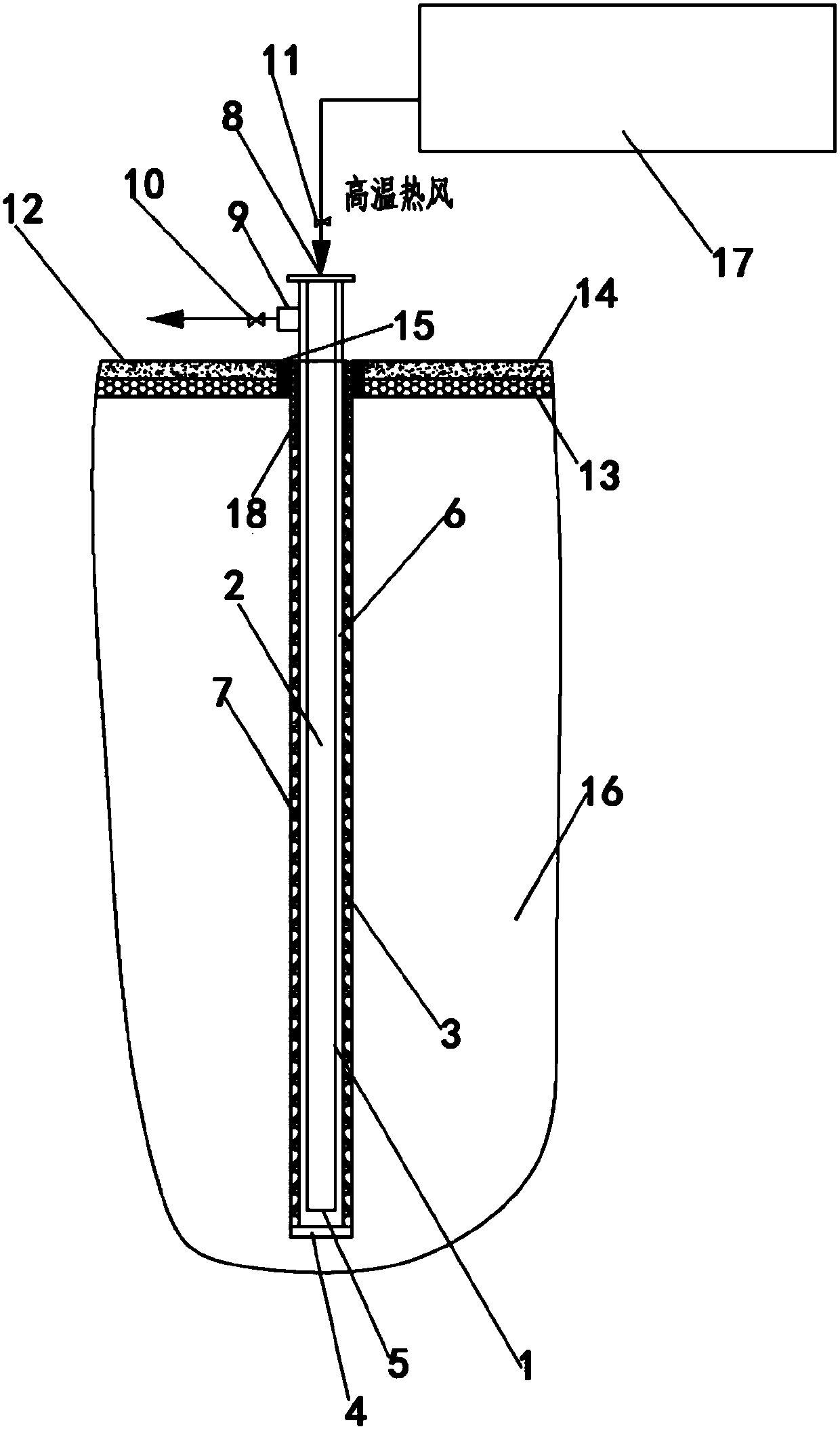
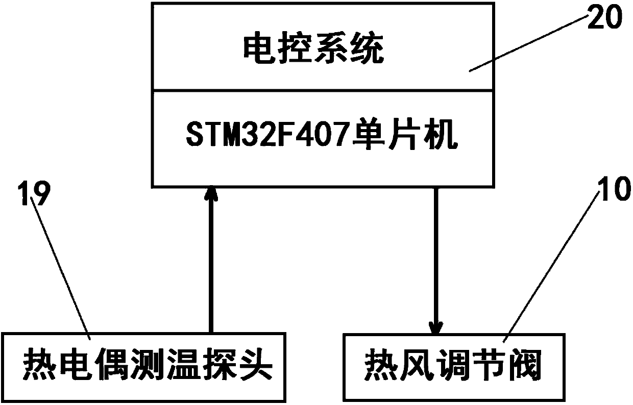
[0029] The heating well 1 is designed with inner and outer concentric casings. The diameter of the outer pipe 3 is 130 cm, and the diameter of the inner pipe 2 is 60 cm. It is made of stainless steel; the bottom of the outer pipe 3 is provided with a bottom cover 4, and the bottom of the inner pipe 2 is an opening 5 without a bottom cover. , 25cm away from the bottom of the outer tube 3. The high-temperature hot air is first fed into the bottom of the heating well 1 through the inner pipe 2 from top to bottom, and then returns to the ground through the gap 6 between the inner pipe 2 and the outer pipe 3 from bottom to top, and is discharged through a hot air outlet 9 arranged on the side. In order to achieve the purpose of equalizing the heat exchange temperature. The hot air outlet 9 is provided with a hot air regulating valve 10 .

[0030] When the heating well 1 is installed, there is generally a 20cm annular gap between the outer pipe 3 and the drilled soil hole, and cera...

Embodiment 2

[0035] The heating well 1 is designed and installed according to the pollution distribution in the in-situ repair area of ​​the polluted site 16 to form a heating well group. The plane adopts the form of dense and uniform distribution of squares, and the well spacing is 1.5m; the vertical direction matches the repair depth and exceeds the pollution. Depth 0.5m.

[0036] According to the distribution of site pollution, the actual conditions of the site and the design characteristics of the system, a hot blast stove 17 is equipped with multiple heating wells 1, and multiple heating wells 1 are operated in parallel, and the amount of hot air entering each heating well 1 is adjusted as much as possible through valves. Possibly balanced.

[0037] The heating well 1 is in the form of inner and outer concentric casings, made of stainless steel; the inner tube 2 has a diameter of 50 cm, and the bottom is an opening 5 without a bottom cover; the outer tube 3 has a diameter of 125 cm, a...


PUM


Abstract

The invention discloses a heating well used for in-situ repair engineering of a contaminated site. The heating well is arranged in the contaminated site from the ground to the underground and is of aninner-outer concentric sleeve structure. The heating well comprises an inner pipe and an outer pipe arranged outside the outer pipe in a sleeving mode. A bottom cover is arranged at the bottom of theouter pipe, and the bottom of the inner pipe is an opening without a bottom cover. A gap is formed between the inner side wall of the outer pipe and the outer side wall of the inner pipe. The outer pipe is mounted in a soil hole downwards pre-formed in the contaminated site from the ground, and a gap between the outer side wall of the outer pipe and the inner wall of the soil hole is filled witha filler. A plurality of different-height thermocouple temperature measuring probes are arranged in the filler. The top end of the heating well is a hot air inlet, and the hot air inlet is connected with a hot air furnace. A hot air exhaust is formed in the side wall, higher than the ground part, of the heating well, and a hot air regulating valve is arranged at the hot air exhaust. The heating well used for in-situ repair engineering of the contaminated site has the outstanding characteristics that the safe and reliable effects are achieved, the thermal desorption temperature is high, the repairing effect is good, and the pollutant concentration after repairing does not bounce.

Description

technical field [0001] The invention relates to a heating device for remediation of polluted sites, in particular to a heating well used for in-situ remediation of polluted sites. Background technique [0002] Thermal Desorption technology can be widely used in in-situ or ex-situ remediation of volatile organic compounds, semi-volatile organic compounds, petroleum hydrocarbons or mercury-contaminated sites. This technology heats the polluted soil and / or groundwater to close to or even exceed the boiling point of the target pollutant by means of direct or indirect heating, and selectively promotes the desorption, gasification, volatilization, Decompose or increase its mobility, so that the target pollutants can be separated from the soil medium and removed, so as to achieve the purpose of remediation of contaminated sites. [0003] The in-situ thermal desorption remediation technology can be implemented in situ on the polluted site without excavating the polluted soil. It is...

Claims


Application Information

Patent Timeline
Patent Type & Authority Applications(China)
IPC IPC(8): B09C1/06
CPCB09C1/065B09C2101/00
Inventor 张峰凃辉王琛马烈王健华顾心爱封卫青
Owner SHANGHAI GREENMENT ENVIRONMENTAL TECH CO L
Why Eureka
Try Eureka