Nuclear fuel cladding pipe and preparation method thereof

A nuclear fuel and cladding tube technology, which is applied in the fields of reactor fuel elements, nuclear engineering, nuclear power generation, etc., can solve the problems of high hardness, inability to process and form, poor plasticity, etc., achieve low operating temperature, good appearance and dimensional accuracy, and ensure smoothness. Effects of degree and roundness

Active Publication Date: 2018-02-13
NAT UNIV OF DEFENSE TECH
View PDF5 Cites 13 Cited by
  • Summary
  • Abstract
  • Description
  • Claims
  • Application Information

AI Technical Summary

Problems solved by technology

Due to the high hardness and poor plasticity of SiC/SiC composite materials, SiC/SiC composite tubular members of such size cannot be prepared by drawing process like zirconium alloys, and SiC/SiC composite tubular

Method used


Image

  • Nuclear fuel cladding pipe and preparation method thereof
  • Nuclear fuel cladding pipe and preparation method thereof
  • Nuclear fuel cladding pipe and preparation method thereof

Examples


Embodiment 1

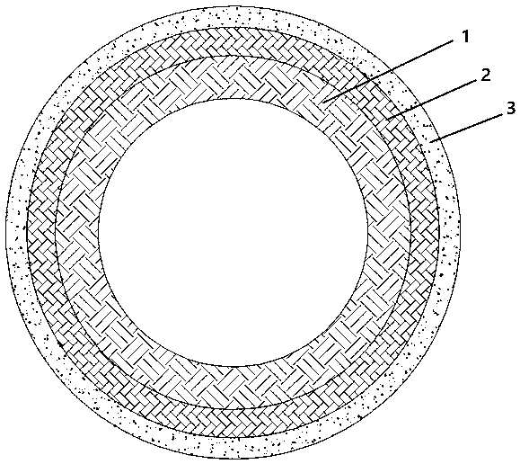
[0035] A nuclear fuel cladding tube, such as figure 1 and 2 As shown, the inner diameter is 9 mm, the length is 70 cm, and the total thickness of the tube wall is 800 μm. The inner layer of the pipe wall is the first SiC / SiC composite material layer 1, the middle layer is the second SiC / SiC composite material layer 2, and the outer layer is a single-phase SiC ceramic layer 3, wherein the first SiC / SiC composite material layer 1 Composed of the first SiC fiber preform and the first SiC ceramic matrix filled in its pores, the second SiC / SiC composite material layer 2 is composed of the second SiC fiber preform and the second SiC ceramic matrix filled in its pores . After the SiC fiber cloth impregnated with epoxy resin glue was wound into a tube, the SiC fiber bundles impregnated with epoxy resin glue were braided at a braiding angle of 45° and wound on the circumference of the fiber cloth winding tube. After curing-carbonization, the first SiC fiber preform and the second Si...

Embodiment 2

[0050] A nuclear fuel cladding tube, which is basically the same as that of Embodiment 1, the only difference is that the inner diameter is 9 mm and the length is 120 cm.

[0051] The preparation method of the nuclear fuel cladding tube of the above-mentioned embodiment is basically the same as that of Embodiment 1, the only difference being that the size of the round rod-shaped stainless steel mandrel is φ9 mm×150 cm.

[0052] The physical figure of the 120 cm nuclear fuel cladding tube prepared in this embodiment is as follows Figure 4 It can be seen from the figure that the wall thickness of the nuclear fuel cladding tube is uniform, the surface is smooth, and there is no local bending along the length direction.


PUM

PropertyMeasurementUnit
The inside diameter ofaaaaaaaaaa
Lengthaaaaaaaaaa
Thicknessaaaaaaaaaa

Abstract

The invention discloses a nuclear fuel cladding pipe and a preparation method thereof. A pipe wall of the nuclear fuel cladding pipe sequentially comprises a first fiber-reinforced ceramic matrix composite layer, a second fiber-reinforced ceramic matrix composite layer and a ceramic layer from inside to outside, wherein the first fiber-reinforced ceramic matrix composite layer is composed of a first fiber prefabricated body and a first ceramic matrix filled into hole gaps of the first fiber prefabricated body, the second fiber-reinforced ceramic matrix composite layer is composed of a second fiber prefabricated body and a second ceramic matrix filled into hole gaps of the second fiber prefabricated body, and the first fiber prefabricated body is formed by winding fiber cloth which is soaked in a resin adhesive into a pipe and curing-carbonizing the pipe, the second fiber prefabricated body is formed by weaving a plurality of fiber bundles which are soaked in the resin adhesive, windingthe fiber bundles on the periphery of the fiber cloth wound pipe and curing-carbonizing the fiber bundles, and the ceramic layer is prepared by a chemical vapor deposition method. The forming methodcan form thin and long fiber-reinforced ceramic matrix composite tubular members in batch; furthermore, the length is not limited, a technology has strong practicability, and an equipment requirementis low.

Description

technical field [0001] The invention belongs to the field of nuclear fuel protection materials, in particular to a nuclear fuel cladding tube and a preparation method thereof. Background technique [0002] The survival and development of human beings are inseparable from energy. With the development of social productivity, human demand for energy is growing rapidly. As a clean and efficient energy source, nuclear energy is considered to be the main way to finally solve human energy problems. Nuclear energy can be divided into fusion reactors and fission reactors based on how they operate. For now, fusion reactors are still in the stage of conceptual design and experimental verification, while fission reactors have been successfully applied widely. In the fission reactor, the nuclear fuel uranium oxide is contained in the cladding tube, and the nuclear fuel undergoes a nuclear reaction in the cladding tube to release heat. The outer side of the cladding tube is a light wat...

Claims


Application Information

Patent Timeline
IPC IPC(8): C04B35/80C04B35/565C04B35/64C04B41/87G21C3/07G21C21/00
CPCC04B35/565C04B35/64C04B35/806C04B41/009C04B41/5059C04B41/87C04B2235/6562G21C3/07G21C21/00C04B41/4531Y02E30/30
Inventor 周新贵黎畅殷刘彦王洪磊余金山
Owner NAT UNIV OF DEFENSE TECH
Why Eureka
Try Eureka