
Track bearing compound blade reciprocating operation multi-unit power generation windmill and direction adjustment method

A technology of reciprocating operation and reciprocating blades, which is applied in the field of power generation windmills, can solve the problems of wasting wind resources and being easily restricted by the terrain of the site, and achieve the effects of good power quality, no harm caused by flying birds, and high efficiency

Active Publication Date: 2019-10-18
刘海龙 +1
View PDF7 Cites 0 Cited by
  • Summary
  • Abstract
  • Description
  • Claims
  • Application Information

AI Technical Summary

Problems solved by technology

[0004] The second is to increase the solidity ratio of windmill blades, so that the same sweeping area can obtain a larger wind-capturing area, which can generate more electricity; while the solidity ratio of traditional windmill blades is between 5% and 20%, a waste of wind resources;
[0006] Chinese Patent No. ZL201410083676.1 patented technology "Two-way counter-rotating circular rail bearing Y-shaped compound blade fluid energy collection multi-unit power generation windmill". Limited by site terrain

Method used


Image

  • Track bearing compound blade reciprocating operation multi-unit power generation windmill and direction adjustment method
  • Track bearing compound blade reciprocating operation multi-unit power generation windmill and direction adjustment method
  • Track bearing compound blade reciprocating operation multi-unit power generation windmill and direction adjustment method

Examples


Embodiment Construction

[0047] In order to make the purpose, technical solution and advantages of the present invention clearer, the technical solution of the present invention will be described in detail below. Apparently, the described embodiments are only some of the embodiments of the present invention, but not all of them. Based on the embodiments of the present invention, all other implementations obtained by persons of ordinary skill in the art without making creative efforts fall within the protection scope of the present invention.

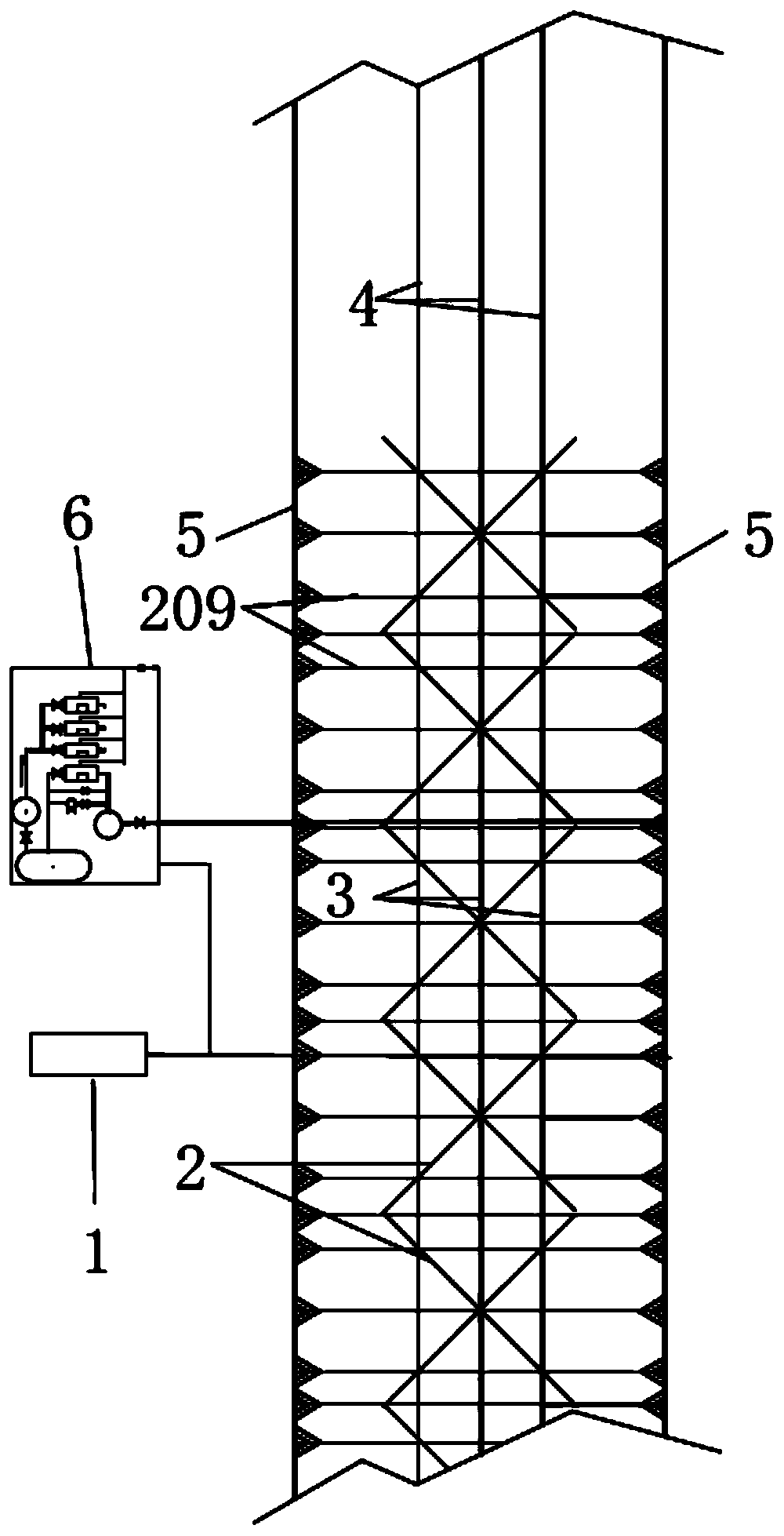
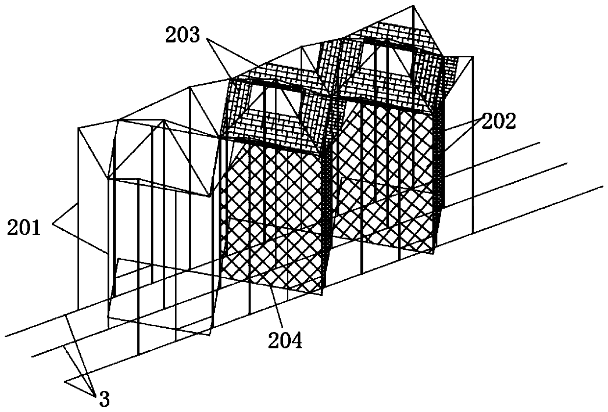
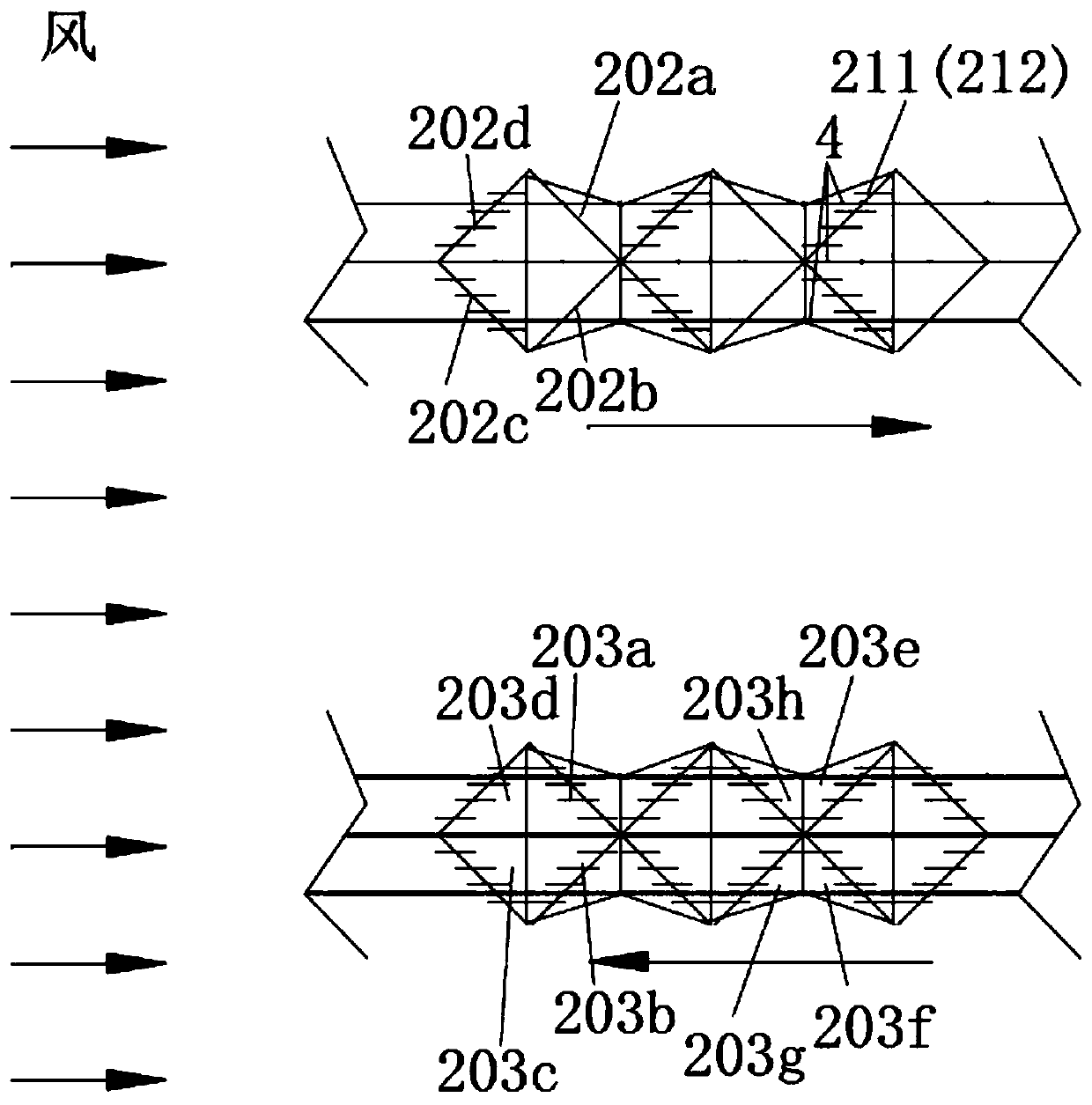
[0048] Such as figure 1 As shown, the rail-carrying compound blades reciprocatingly operate the air pressure energy collection and energy storage multi-unit power generation windmill, including the remote automatic control system 1 of the windmill, the square conjoined compound blade 2 composed of single blades, the windmill body 3 carrying the compound blades, and the support The windmill track 4 that the windmill car body runs, the cable car 5 that runs on th...


PUM


Abstract

Disclosed are a multi-unit power generation windmill using a track-borne compound blade reciprocating operation, and a direction adjusting method. The multi-unit power generation windmill using a track-borne compound blade reciprocating operation comprises a remote automatic windmill control system (1), a square conjoined compound blade (2) formed of a combination of single blades, a windmill body (3) for bearing the compound blade, a windmill track (4) for supporting the operation of the windmill body, cable vehicles (5) operating on a cable vehicle track, and a pneumatic energy collection multi-unit power generation system (6). The windmill operates both downwind and upwind. When the windmill operates downwind, the kinetic energy of the windmill body (3) is converted into pneumatic force energy depending on an air pump (601), and the pneumatic force energy is stored in an air reservoir (604). When the windmill operates upwind, high-pressure air energy stored in the air reservoir (604) is converted into the kinetic energy for operation of the windmill body (3) depending on a pneumatic motor (602). The high-pressure air energy stored in the air reservoir (604) is continuously converted into power by means of a turbine generator (616).

Description

technical field [0001] The invention belongs to the new technology of utilizing renewable clean energy—wind energy, and relates to a high-power windmill for power generation, which is characterized in that the track carries compound blades in an innovative design, the windmill reciprocates along the track, and uses air pressure to collect energy and compressed air to store energy The multi-unit power generation system generates electricity, produces more electric energy, and can utilize wind energy on a large scale and with high efficiency. Background technique [0002] In the past, windmills for power generation were single-tower windmills with small power generation and low power generation efficiency. The main technical problems were as follows: [0003] One is that expanding the diameter of the wind rotor in proportion can generate more power, which will also bring about a substantial increase in the weight of the wind rotor and generator, and the increase in bearing loa...

Claims


Application Information

Patent Timeline
Patent Type & Authority Patents(China)
IPC IPC(8): F03D9/17F03D5/04F03D7/00
CPCF03D5/04F03D7/00F03D9/17Y02E10/70Y02E10/72Y02E60/16Y02E70/30
Inventor 刘海龙展巍
Owner 刘海龙
Learn More