
Boiler full-load denitration coupling flue gas waste heat gradient utilization system

A flue gas waste heat, full-load technology, applied in preheating, lighting and heating equipment, combustion methods, etc., can solve the problems of low efficiency and low energy level

Pending Publication Date: 2018-02-13
SHANDONG HONGAO POWER TECHNOLOGY CO LTD
View PDF11 Cites 10 Cited by
  • Summary
  • Abstract
  • Description
  • Claims
  • Application Information

AI Technical Summary

Problems solved by technology

The conventional way to recover flue gas waste heat is to arrange a low-temperature economizer in the flue, and add condensate water at the end of the heating stage. On the surface, a large amount of flue gas waste heat can be recovered, but the energy level of the waste heat is low, resulting in the return point of condensate water and The location of the extraction point can only be upgraded by one or two levels of low-addition, so the benefits generated are low

Method used


Image

  • Boiler full-load denitration coupling flue gas waste heat gradient utilization system

Examples


Embodiment Construction

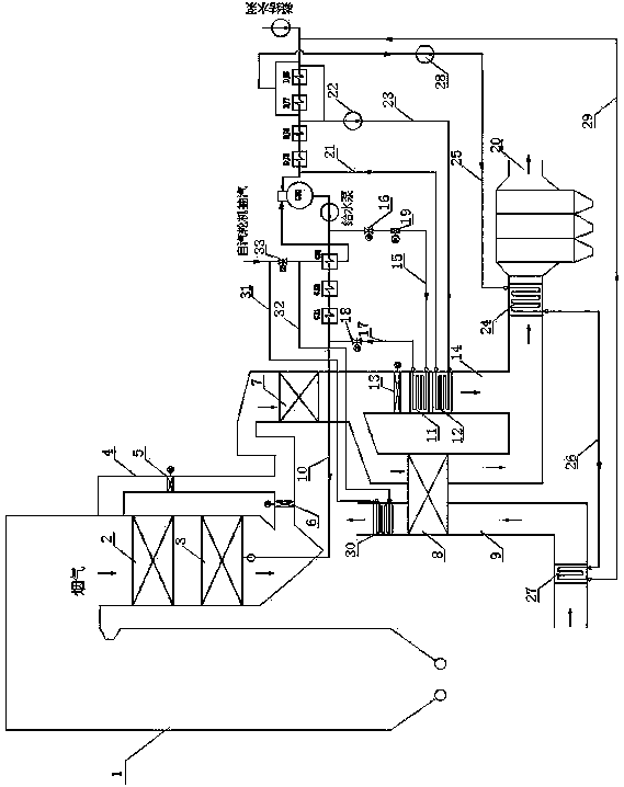
[0025] Accompanying drawing is a kind of specific embodiment of the present invention. This embodiment includes a boiler 1 connected to an air supply pipe 9. A low-temperature heater 2, an economizer 3, a denitrification device 7, an air preheater 8, and an electric precipitator are sequentially installed in the flue gas passage of the boiler 1 along the advancing direction of the flue gas. 20, wherein the air preheater 8 is installed in the air supply pipe 9 at the same time, and the flue gas channel is provided with a high-temperature denitration bypass flue 4 between the entrance of the low-temperature superheater 2 and the entrance of the denitration device 7, and the high-temperature denitration bypass The bypass flue cut-off baffle A5 is set in the road flue 4, the main flue adjustment baffle 6 at the outlet of the economizer 3 and the low-temperature economizer at the entrance of the electrostatic precipitator 20 are installed in the flue gas channel 24. The flue gas ch...


PUM


Abstract

The invention relates to the field of boiler full-load denitration putting-into-operation and exhausted smoke waste heat utilization and particularly discloses a boiler full-load denitration couplingflue gas waste heat gradient utilization system. The boiler full-load denitration coupling flue gas waste heat gradient utilization system comprises a boiler; a low-temperature heater, a coal economizer, a denitration device, an air preheater and an electric dust remover are sequentially mounted in a flue gas channel of the boiler in the advancing direction of flue gas. The boiler full-load denitration coupling flue gas waste heat gradient utilization system is characterized in that a high-temperature denitration bypass flue is arranged in the position, between an inlet of the low-temperatureheater and an inlet of the denitration device, of the flue gas channel; an air preheater bypass flue is arranged in the position, between an outlet of the denitration device and an inlet of the electric dust remover, of the flue gas channel; and a high-temperature coal economizer and a medium-temperature coal economizer are sequentially arranged in the air preheater bypass flue in the advancing direction of the flue gas. According to the boiler full-load denitration coupling flue gas waste heat gradient utilization system, the denitration device can be effectively put into use under the low load condition of the boiler, and the splitting problem of the denitration device due to decreasing of the load of the boiler is solved; and gradient utilization of waste heat of the flue gas is achieved, high energy level extracted steam is effectively squeezed out, the power generation load is increased, and the overall benefits of a power plant are promoted.

Description

(1) Technical field [0001] The invention relates to the fields of boiler full-load denitrification and waste heat utilization, in particular to a boiler full-load denitrification coupled flue gas waste heat cascade utilization system. (2) Background technology [0002] At present, domestic thermal power plants widely use SCR (Selective Catalytic Reduction) to control NOx emissions, and the optimal reaction temperature range of the catalyst is 300°C to 420°C. The flue gas temperature at the inlet of the denitrification device changes with the boiler load. When the boiler load is low, the flue gas temperature at the inlet of the denitrification device is low. On the one hand, the activity of the catalyst will be reduced. SO 3 The ammonia bisulfate produced by the reaction will be deposited on the catalyst, further reducing the activity of the catalyst, and even causing an irreversible reduction in the activity of the catalyst. [0003] In addition, among the various heat los...

Claims


Application Information

Patent Timeline
Patent Type & Authority Applications(China)
IPC IPC(8): F22D11/06F23L15/00F23J15/00
CPCF22D11/06F23J15/006F23L15/00Y02E20/34
Inventor 齐林虎李忠江黄新元刘红英石长江
Owner SHANDONG HONGAO POWER TECHNOLOGY CO LTD
Learn More