Multiple-valued heat-insulation multiplier unit circuit based on transmission gate structure

A unit circuit and multiplier technology, which is applied in the direction of instruments, electrical digital data processing, digital data processing components, etc., can solve the problems of multiplier unit circuit area, power consumption and operation cycle, etc.

Active Publication Date: 2018-02-13
NINGBO UNIV
View PDF4 Cites 2 Cited by
  • Summary
  • Abstract
  • Description
  • Claims
  • Application Information

AI Technical Summary

Problems solved by technology

[0003] With the development of integrated circuit technology, the requirements for multiplier units are getting higher and higher. It is becoming more and more difficult for traditional multiplier unit circuits implemented by CMO

Method used


Image

  • Multiple-valued heat-insulation multiplier unit circuit based on transmission gate structure
  • Multiple-valued heat-insulation multiplier unit circuit based on transmission gate structure
  • Multiple-valued heat-insulation multiplier unit circuit based on transmission gate structure

Examples


Embodiment 1

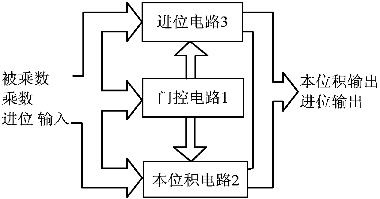
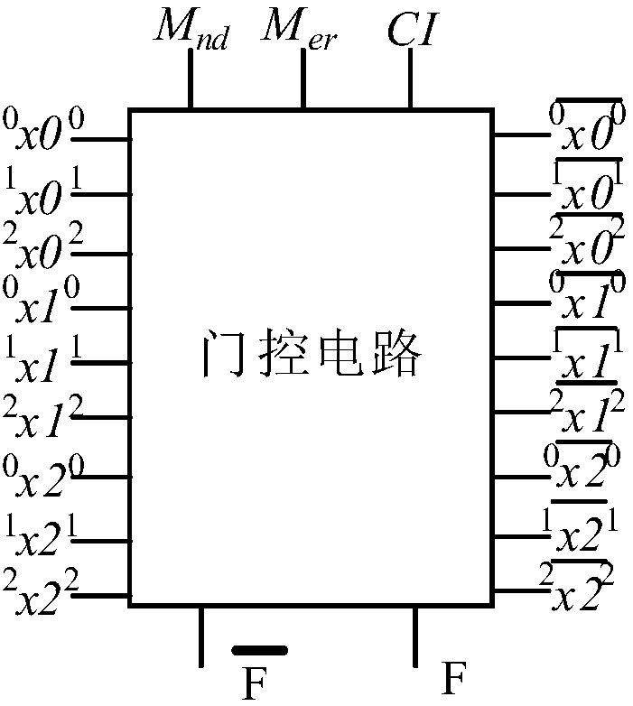
[0025] Embodiment one: if figure 1 , Figure 2(a) and Image 6 As shown, a multi-valued adiabatic multiplier unit circuit based on the transmission gate structure includes a gate control circuit 1, a potential product circuit 2 and a carry circuit 3, and the gate control circuit 1 has a first input terminal, a second input terminal, a third input terminal, first output terminal, second output terminal, third output terminal, fourth output terminal, fifth output terminal, sixth output terminal, seventh output terminal, eighth output terminal, ninth output terminal, first Inversion output terminal, second inversion output terminal, third inversion output terminal, fourth inversion output terminal, fifth inversion output terminal, sixth inversion output terminal, seventh inversion output terminal, eighth inversion output terminal phase output terminal, ninth inverting output terminal, clock control clock signal input terminal and power clock signal input terminal; this volume pro...

Embodiment 2

[0031] Embodiment 2: This embodiment is basically the same as the embodiment, the difference is that in this embodiment, such as Figure 7 As shown, the two-input AND gate AND1 includes a thirty-seventh PMOS transistor P37, a thirty-eighth PMOS transistor P38, a thirty-ninth PMOS transistor P39, a thirty-seventh NMOS transistor N37, a thirty-eighth NMOS transistor N38, and a thirty-eighth NMOS transistor N38. The thirty-ninth NMOS transistor N39, the source of the thirty-seventh PMOS transistor P37, the source of the thirty-eighth PMOS transistor P38 and the source of the thirty-ninth PMOS transistor P39 are all connected to the power supply, the thirty-seventh PMOS transistor The gate of P37 is connected to the gate of the thirty-seventh NMOS transistor N37 and its connection end is the first input end of the two-input AND gate AND1, the gate of the thirty-eighth PMOS transistor P38 is connected to the thirty-eighth NMOS transistor N38 and its connection end is the second inp...


PUM


Abstract

The invention discloses a multiple-valued heat-insulation multiplier unit circuit based on a transmission gate structure. The multiple-valued heat-insulation multiplier unit circuit based on the transmission gate structure comprises a gating circuit, a standard integral circuit and a carry circuit, wherein the gating circuit is separately connected with the standard integral circuit and the carrycircuit; and two multiplicator and low carry signals are connected into the gating circuit, a character control signal is generated and is output to the standard integral circuit and the carry circuit, the standard integral circuit outputs a standard integral signal, and the carry circuit outputs a high carry signal. The multiple-valued heat-insulation multiplier unit circuit based on the transmission gate structure has the advantages that the standard integral circuit and the carry circuit are implemented by a full-heat-insulation mode, charge in the standard integral circuit and the carry circuit is recycled in a full heat-insulation recovery mode, power consumption of the circuit is reduced, meanwhile, multi-valued signals in the standard integral circuit and the carry circuit are implemented by a gating circuit switch controlled binary mode, the working speed of the circuit can be increased, the operation cycle is shortened, the hardware cost of the circuit is reduced, and the areais small.

Description

technical field [0001] The invention relates to a multi-value adiabatic multiplier unit circuit, in particular to a multi-value adiabatic multiplier unit circuit based on a transmission gate structure. Background technique [0002] In the development of VLSI, the multiplier is the core of real-time image processing and digital signal processing, and is often the key path of data processing in microprocessors. The period in which the multiplier completes one operation basically determines the main frequency of the microprocessor. Therefore, the research and implementation of high-performance multipliers are very important for microprocessors. The multiplier unit circuit is an important computing unit for building a multiplier, and its performance improvement plays an important role in improving the overall performance of the multiplier. The multiplication operation in the multiplier unit circuit is based on a large number of addition operations, and the basic steps to compl...

Claims


Application Information

Patent Timeline
IPC IPC(8): G06F7/523
CPCG06F7/523
Inventor 张跃军王佳伟丁代鲁潘钊
Owner NINGBO UNIV
Why Eureka
Try Eureka