Power control method and device, inverter device and power station controller
A power control and inverter technology, applied in the field of communication, can solve the problems of increasing the investment cost of photovoltaic station construction and operation and maintenance costs
- Summary
- Abstract
- Description
- Claims
- Application Information
AI Technical Summary
Problems solved by technology
Method used
Image

Examples
Embodiment 1
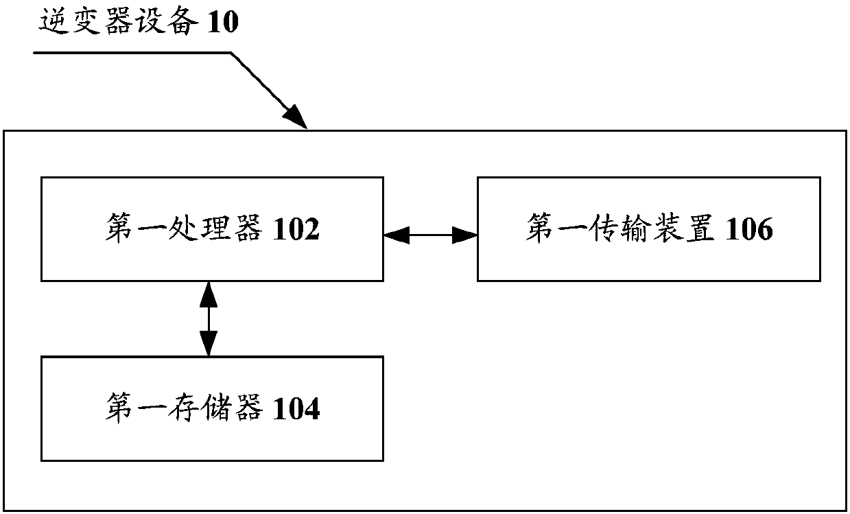
[0055] The method embodiment provided in Embodiment 1 of the present application may be executed in an inverter device or a similar computing device. Take running on the inverter device as an example, figure 1 It is a hardware structural frame of an inverter device according to a power control method in an embodiment of the present invention Figure 1 . Such as figure 1 As shown, the inverter device 10 may include one or more (only one is shown in the figure) first processor 102 (the first processor 102 may include but not limited to microprocessor MCU or programmable logic device FPGA, etc. processing means), a first memory 104 for storing data, and a first transmission means 106 for communication functions. Those of ordinary skill in the art can understand that, figure 1 The shown structure is only for illustration, and it does not limit the structure of the above-mentioned electronic device. For example, the inverter device 10 may also include a ratio figure 1 more or...
Embodiment 2
[0117] The method embodiment provided in Embodiment 2 of the present application may be executed in an inverter device or a similar computing device. Take running on the inverter device as an example, Figure 6 It is the hardware structural frame of the power station controller of a power control method in the embodiment of the present invention Figure II . Such as Figure 6 As shown, the power plant controller 60 may include one or more (only one is shown in the figure) second processors 602 (the second processors 602 may include but not limited to microprocessor MCU or programmable logic device FPGA, etc. device), a second memory 604 for storing data, and a second transmission device 606 for communication functions. Those of ordinary skill in the art can understand that, Figure 6 The shown structure is only for illustration, and it does not limit the structure of the above-mentioned electronic device. For example, the plant controller 60 may also include a ratio Fig...
Embodiment 3
[0161] In this embodiment, a power control device is also provided, which is used to implement the above embodiments and preferred implementation modes, and what has been explained will not be repeated here. As used below, the term "module" may be a combination of software and / or hardware that realizes a predetermined function. Although the devices described in the following embodiments are preferably implemented in software, implementations in hardware, or a combination of software and hardware are also possible and contemplated.
[0162] Figure 12 is the structural frame of the power control device according to the embodiment of the present invention Figure 1 ,Such as Figure 12 As shown, the device includes:
[0163] The receiving module 122 is used for the inverter device to receive the control instruction, wherein the control instruction carries the first parameter for determining the reactive power compensation amount of the inverter device to compensate the reactiv...
PUM
 Abstract
Description
Claims
Application Information
 - R&D
- Intellectual Property
- Life Sciences
- Materials
- Tech Scout
- Unparalleled Data Quality
- Higher Quality Content
- 60% Fewer Hallucinations
Browse by: Latest US Patents, China's latest patents, Technical Efficacy Thesaurus, Application Domain, Technology Topic, Popular Technical Reports.
© 2025 PatSnap. All rights reserved.Legal|Privacy policy|Modern Slavery Act Transparency Statement|Sitemap|About US| Contact US: help@patsnap.com