
Laser-air water coaxial jet coupling head and underwater laser machining device

A coaxial jet and processing device technology, applied in the direction of metal processing equipment, laser welding equipment, manufacturing tools, etc., can solve the problems of difficult to accurately control the focus accuracy and position, fast energy dissipation, and affect the processing quality, etc., to achieve focus control accuracy Reduced requirements, simple device structure, and low cost

Inactive Publication Date: 2018-02-16
HUAZHONG UNIV OF SCI & TECH
View PDF13 Cites 12 Cited by
  • Summary
  • Abstract
  • Description
  • Claims
  • Application Information

AI Technical Summary

Problems solved by technology

[0007] In general, the current underwater laser processing has the following problems: (1) seawater and ocean currents will affect the focusing control of the laser beam, making it difficult to precisely control the focusing accuracy and position, which will affect the processing quality; (2) the liquid jet will form a submerged The jet flow makes the energy dissipate quickly, and it cannot form the free liquid surface required for total reflection. (3) The underwater processing device is easily eroded by seawater, and the watertightness of the device is high.
At present, there is no mature laser processing device that can be applied underwater. Further improvement and improvement are urgently needed in this field. A device suitable for underwater laser processing is designed to prevent seawater from focusing on laser processing. The influence of point position accuracy control and the influence on workpiece processing quality

Method used


Image

  • Laser-air water coaxial jet coupling head and underwater laser machining device
  • Laser-air water coaxial jet coupling head and underwater laser machining device

Examples


Embodiment

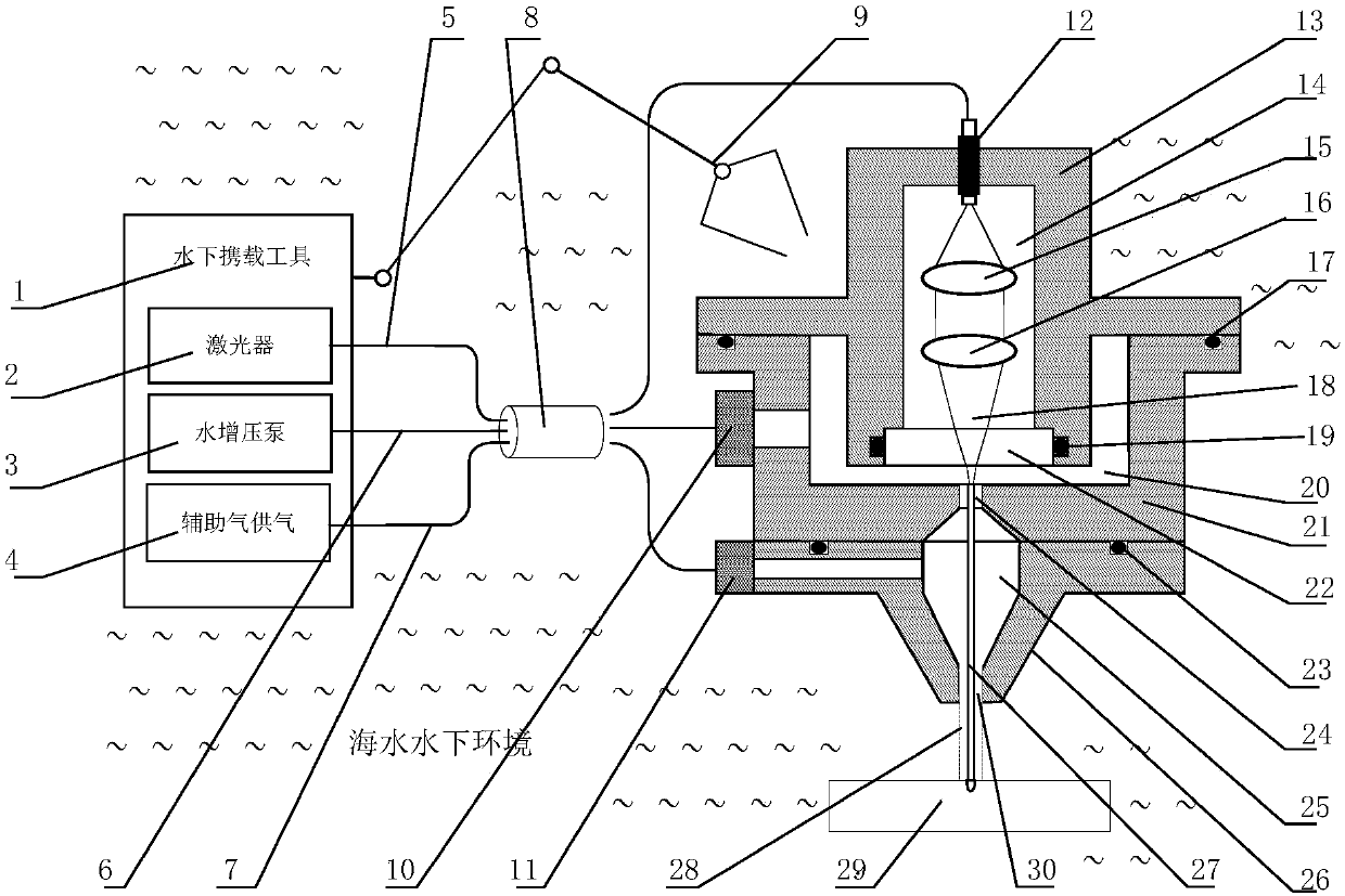
[0049] Such as figure 1 Shown is a kind of underwater air-water coaxial jet assisted laser processing device of the present invention, and its concrete composition is as follows:

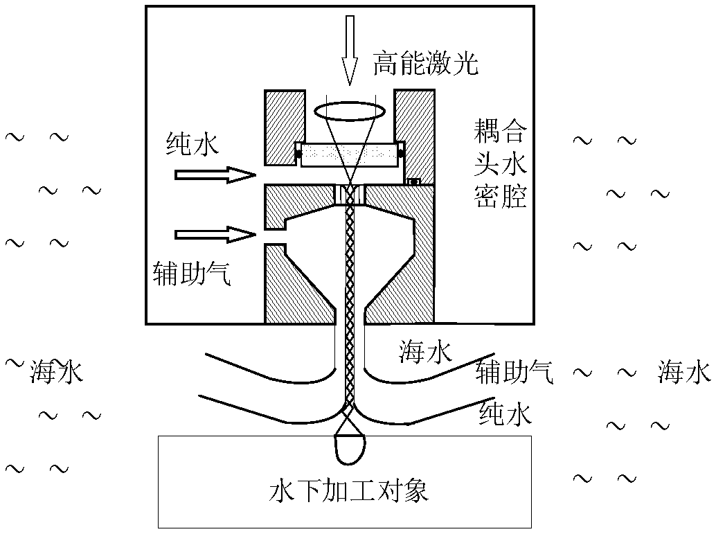
[0050] The device mainly includes a laser-air-water coaxial jet coupling head, a laser 2 and an optical path system, a water booster pump 3, and an auxiliary gas supply device 4. The whole set of devices can be carried to the underwater processing site by the underwater carrier 1 . The laser-air-water coaxial jet coupling head is composed of a laser optical path watertight cavity 14 with a working water depth and watertight design, a high-pressure water cavity 20 and an auxiliary air-scavenging cavity 25 . The coupling head moves and processes under the operation of the mechanical arm and the clamping mechanism 9 . The laser 2 and the optical path system provide laser irradiation required for processing. The water booster pump 3 provides the boosted pure water needed for jet flow. Auxiliary air ...


PUM


Abstract

The invention belongs to the field of underwater laser machining, and particularly discloses a laser-air water coaxial jet coupling head and an underwater laser machining device. The coupling head comprises a laser adjusting device, a high-pressure water cavity wall and an auxiliary air cavity wall which are arranged coaxially in sequence. An energy transmission optical fiber splice, a collimatinglens, a focusing lens, a laser window, a water jet nozzle and an air water coaxial jet nozzle are all located on the axis of the coupling head. Laser beams introduced from the energy transmission optical fiber splice are jet out after passing through the collimating lens and the focusing lens in sequence, form light-water coupling jet flow with water jet flow, and then form coaxial jet flow withair jet flow, then the coaxial jet flow is sprayed out, and then a machined component is machined. The invention further discloses an underwater air water coaxial jet flow auxiliary laser machining device. According to the coupling head and the auxiliary laser machining device, requirements for the underwater laser focusing control precision can be lowered, influences of seawater on the laser beams, high-pressure jet water beams and the machining quality can be isolated, and meanwhile, the advantages that the device is simple in structure, low in cost, easy to operate and the like are achieved.

Description

technical field [0001] The invention belongs to the field of underwater laser processing, and more specifically relates to a laser-air-water coaxial jet coupling head and an underwater laser processing device, which can couple high-energy laser into the air-water coaxial jet, thereby reducing the impact on the laser. The processing focuses on the requirements of precision control and improves the processing quality. Background technique [0002] Laser processing has been widely used in onshore workpiece cutting, drilling, welding, cleaning, and surface treatment. When working underwater, due to the influence of the water environment, the structure, control and even the interaction of the laser material of the processing object are very different from those of land-based laser processing equipment and processing quality. The watertightness of the equipment, the precision of motion control, the structure and weight of the equipment itself, the transmission of the laser and th...

Claims


Application Information

Patent Timeline
Patent Type & Authority Applications(China)
IPC IPC(8): B23K26/00B23K26/122B23K26/70
CPCB23K26/00B23K26/1224B23K26/702
Inventor 刘炎
Owner HUAZHONG UNIV OF SCI & TECH
Learn More