
Multistage reverse cycle ammonia absorption process

A process and ammonia recycling technology, applied in ammonia compound, chemical industry, ammonia preparation/separation, etc., can solve the problems of insufficient ammonia absorption, low work efficiency and high process cost, saving labor cost and reducing process cost , the effect of improving process efficiency

Active Publication Date: 2018-02-16
SICHUAN JUHONG TECH
View PDF13 Cites 1 Cited by
  • Summary
  • Abstract
  • Description
  • Claims
  • Application Information

AI Technical Summary

Problems solved by technology

[0005] The purpose of the present invention is to overcome the above-mentioned deficiencies in the prior art, provide a multi-stage reverse cycle ammonia absorption process, solve the waste of heat and insufficient ammonia absorption in the traditional high-level ammonia absorption method, and transfer out the process in batches High cost and low work efficiency

Method used


Image

  • Multistage reverse cycle ammonia absorption process
  • Multistage reverse cycle ammonia absorption process
  • Multistage reverse cycle ammonia absorption process

Examples


Embodiment 1-1

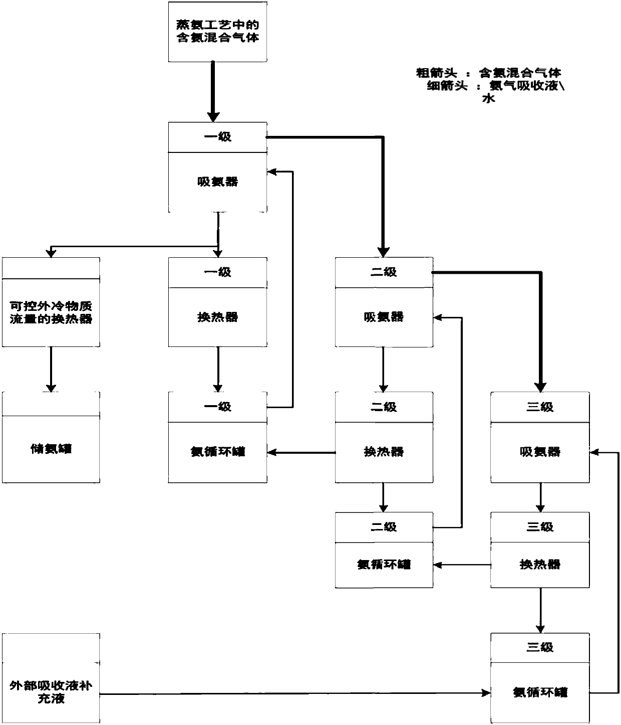
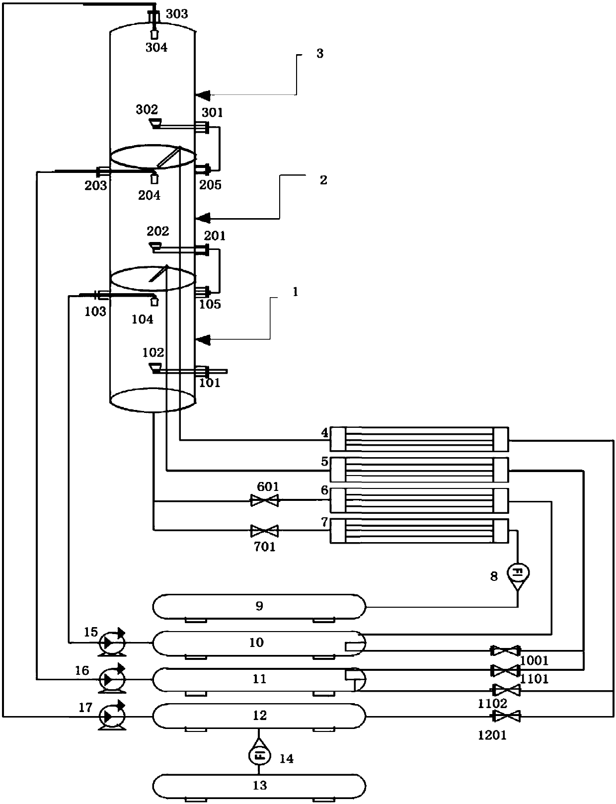
[0053] Such as figure 2 As shown, the ammonia concentration is 0.595kg / m 3 Process gas mixture, according to 850.9m 3 The flow rate of / h is passed into the primary ammonia absorbing monomer 1, and the primary process water pump 15, the secondary process water pump 16, and the tertiary process water pump 17 are turned on simultaneously. The three-stage process water pump 17 pumps the clear water in the external process circulating water tank 13 into the three-stage ammonia absorbing monomer 3; the process mixed gas in the first-stage ammonia absorbing monomer 1 enters the three-stage ammonia absorbing monomer 3, and is absorbed The ammonia-absorbing liquid formed after the clear water is absorbed flows back into the secondary ammonia-absorbing circulating tank 11 and the third-stage ammonia-absorbing circulating tank 12 respectively; Pumped by the secondary process water pump 16 into the secondary ammonia-absorbing monomer 2 to absorb ammonia, the ammonia-absorbing liquid f...

Embodiment 1-2

[0057] Take the operation steps described in Experimental Example 1-1, the difference is: the ammonia concentration is 0.578kg / m 3 Process gas mixture, according to 867.2m 3 The flow rate of / h is passed into the primary ammonia absorbing monomer 1, and the valves that control the return flow of the ammonia absorbing liquid in the branches of each return pipeline are continuously adjusted, and combined with the detection of flowmeter one 8 and flowmeter two 14 Observe, finally make the absorption liquid in the first-level ammonia absorption circulation tank 10 be the ammonia absorption liquid (concentration value: 108.5tt) of high concentration, the absorption liquid in the secondary ammonia absorption circulation tank 11 is the ammonia absorption liquid of medium concentration ( The concentration value is: 57.4tt), and the absorption liquid in the three-stage ammonia absorption circulation tank 12 is a low-concentration ammonia absorption liquid (concentration value: 24.1tt),...

Embodiment 1-3

[0061] Take the operating steps described in Example 1-1, the difference is: the ammonia concentration is 0.604kg / m 3 Process gas mixture, according to 821.6m 3The flow rate of / h is passed into the primary ammonia absorbing monomer 1, and the valves that control the return flow of the ammonia absorbing liquid in the branches of each return pipeline are continuously adjusted, and combined with the detection of flowmeter one 8 and flowmeter two 14 Observe, finally make the absorption liquid in the first-level ammonia absorption circulation tank 10 be the ammonia absorption liquid (concentration value: 102.1tt) of high concentration, the absorption liquid in the secondary ammonia absorption circulation tank 11 is the ammonia absorption liquid of medium concentration ( The concentration value is: 53.8tt), and the absorption liquid in the three-stage ammonia absorption circulation tank 12 is a low-concentration ammonia absorption liquid (concentration value: 22.8tt). The statisti...


PUM


Abstract

The invention discloses a multistage reverse cycle ammonia absorption process which comprises multistage ammonia absorption cycle sections performed simultaneously. The process comprises the followingsteps: sequentially dividing each stage of the ammonia absorption cycle into 1, 2, ..., N stages of ammonia absorption cycles according to a higher concentration to a lower concentration of ammonia absorption liquid, enabling to-be-absorbed ammonia-containing mixed gas to sequentially flow through 1 to N stages of ammonia absorption cycle sections, absorbing ammonia absorption liquid with a highammonia-containing concentration, enabling incompletely absorbed gases to enter an adjacent lower stage ammonia absorption cycle section, and absorbing ammonia absorption liquid with a low ammonia-containing concentration; respectively enabling the ammonia absorption liquid in each stage of the ammonia absorption cycle to return to the local stage and the adjacent upper stage of the ammonia cycletanks so as to serve as replenishing liquor of the ammonia absorption liquid, wherein the N-stage ammonia absorption liquid is directly supplemented by external ammonia absorption liquid; and performing heat exchange treatment at controllable intensity on ammonia absorption liquid of which the ammonia-containing concentration reaches a specified value in the 1-stage ammonia absorption cycle section. Therefore, automatic continuous output of ammonia recycled liquid with a qualified concentration and a high temperature is realized. The multistage reverse cycle ammonia absorption process disclosed by the invention has the characteristics of being high in ammonia absorption rate, simple in operation, energy-saving and consumption-reducing.

Description

technical field [0001] The invention relates to an ammonia absorption method in an ammonia distillation process, in particular to a multi-stage reverse cycle ammonia absorption process in an ammonia zinc oxide process. Background technique [0002] The process of ammonia zinc oxide is a cycle of ammonia. Ammonia water is used for zinc complexation, and ammonia steam is used to realize the crystallization of zinc ions. After ammonia gas is converted into ammonia water by ammonia absorption, it can be used as zinc ammonia complex. The solution is used for the complexation of zinc. The maximum energy consumption of the ammonia-based zinc oxide process is the steam used for ammonia distillation. In a high-efficiency ammonia distillation device, the steam energy consumed by heating the zinc-ammonia complex solution from room temperature to boiling accounts for 50% of the evaporation consumption of the entire process. [0003] In the traditional ammonia-based zinc oxide process, ...

Claims


Application Information

Patent Timeline
Patent Type & Authority Applications(China)
IPC IPC(8): C01C1/02C01G9/02
CPCC01C1/022C01G9/02Y02P20/50
Inventor 王吉白李时春
Owner SICHUAN JUHONG TECH
Learn More