A flange with an anti-slip grooved gasket and a pressure sensor and its manufacturing method

A technology of pressure sensor and anti-slip groove, which is applied in the direction of manufacturing tools, additive manufacturing, instruments, etc., can solve problems such as pipeline gas or liquid leakage, pre-tightening force is too loose, equipment failure, etc., to improve reliability, prevent loosening, The effect of long working life

Active Publication Date: 2021-04-13
JIANGYIN HENGRUN HEAVY IND
View PDF23 Cites 0 Cited by
  • Summary
  • Abstract
  • Description
  • Claims
  • Application Information

AI Technical Summary

Problems solved by technology

However, due to factors such as thermal deformation, load changes, and vibrations that may occur during the operation of the equipment, or due to the influence of bolt or washer corrosion, the pre-tightening force of the bolts may change, causing the pre-tightening force to be too loose or too tight.
Too tight bolt pre-tightening force will cause the bolt to overload and break, and too loose bolt pre-tightening force will further loosen the bolt, both of which will lead to equipment failure, and even lead to major equipment safety accidents in severe cases
[0004] Therefore, for occasions that require high reliability applications, such as occasions that may cause the leakage of toxic gas or liquid in the pipeline or nuclear leakage, only relying on the initial preload setting during equipment installation is far from meeting the requirements of the equipment operating conditions. For this reason, it is urgent to develop a technology that can dynamically monitor the bolt pre-tightening force during equipment installation and use.

Method used


Image

  • A flange with an anti-slip grooved gasket and a pressure sensor and its manufacturing method
  • A flange with an anti-slip grooved gasket and a pressure sensor and its manufacturing method
  • A flange with an anti-slip grooved gasket and a pressure sensor and its manufacturing method

Examples


Embodiment 1

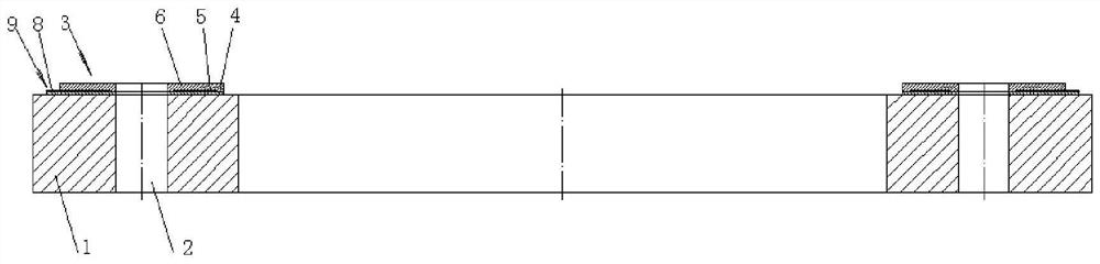
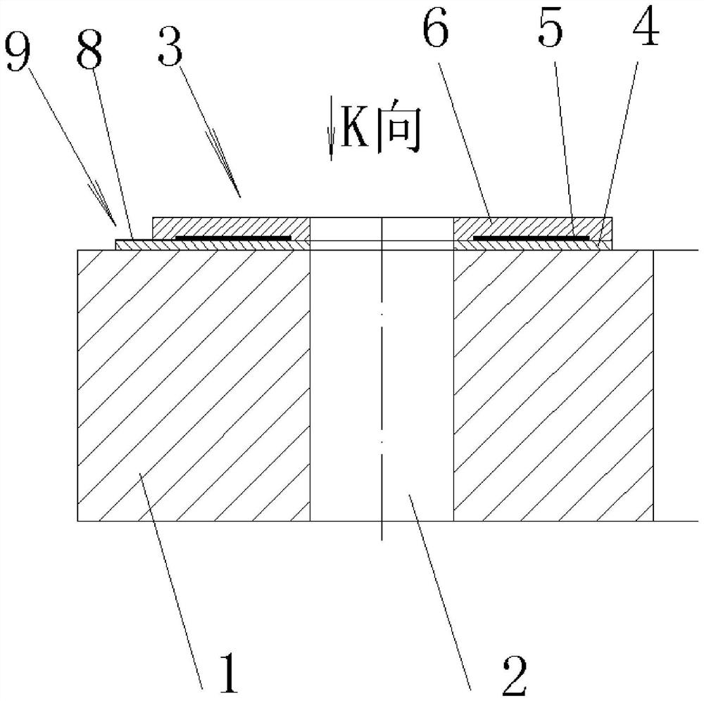
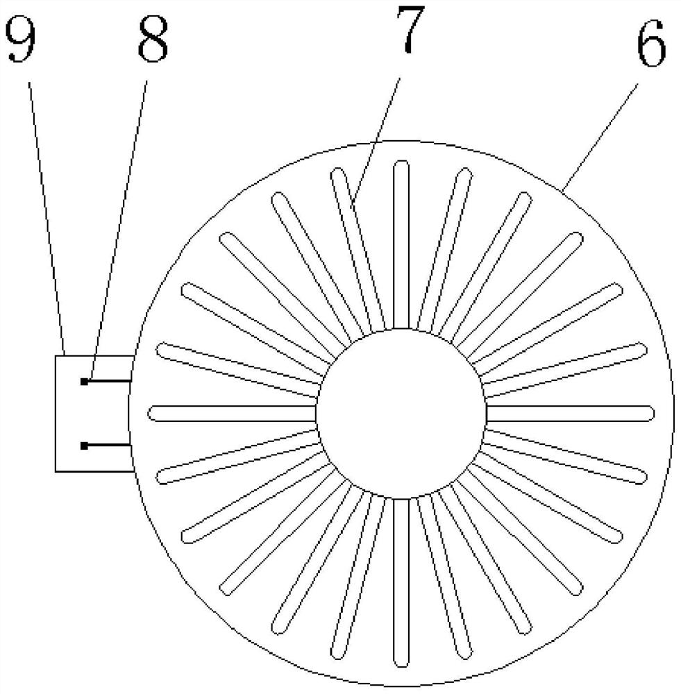
[0036]Such asFigure 1 to 4The illustrated embodiment of the present invention is a flange of a non-slip groove type gasket with a pressure sensor, including the flange 1, the bolt mounting hole 2 provided on the flange 1, located on the flange 1 in a bolt An annular gasket 3 is integrated on the end face of the mounting hole 2, and the annular gasket 3 includes a non-conductive underlayer 4, a metal resistance strain sheet 5, a non-conductive anti-skid layer 6, the bottom layer 4 and a bolt mounting hole. The end surface of 2 is combined with the bottom layer 4, and the anti-slip layer 6 is combined with the metal resistance strain layer 5, and a non-slip groove 7 is provided on the anti-slip surface of the anti-slip layer 6.

[0037]As one of the preferred embodiments of the present embodiment, the metal resistance strain sheet 5 is a foil metal strain piece and is provided with two extraction terminals 8.

[0038]As a preferred embodiment of the present embodiment, the metal resistance ...

Embodiment 2

[0044]The method of manufacturing the flange of the above Example 1 includes the following process steps:

[0045]Step 1, the flange blank is made, the blank is a metal blank, the metal blank is any one of forgings, sheets, and castings;

[0046]Step 2, machine processing flange outer circles, inner holes and two end faces;

[0047]Step 3, machining bolt mounting holes;

[0048]Step 4, perform the computer 3D shape of the annular gasket, 3D modeling data input 3D printer;

[0049]Step 5, use a 3D printer printing the bottom layer of the ring gasket;

[0050]Step 6, printing a metal resistance strain layer using a 3D printer;

[0051]Step 7, a non-slip layer of the annular gasket is printed with a 3D printer, and the non-slip layer comprises a non-slip groove.


PUM


Abstract

The invention relates to the technical field of flanges, in particular to a flange with an anti-skid groove type gasket and a pressure sensor and a manufacturing method. A flange with an anti-slip grooved gasket and a pressure sensor, comprising a flange and a bolt installation hole provided on the flange, and an annular gasket integrated on the end surface of the bolt installation hole on the flange, The annular gasket comprises a non-conductive bottom layer, a metal resistance strain gauge layer, and a non-conductive anti-skid layer in turn, the bottom layer is combined with the end face of the bolt mounting hole, the metal resistance strain gauge layer is combined with the bottom layer, and the anti-skid layer The layer is combined with the metal resistance strain gauge layer, and an anti-skid groove is provided on the anti-skid surface of the anti-skid layer. In the present invention, a washer with a built-in metal resistance strain gauge is integrally arranged on the bolt hole of the flange, the pressure of the bolt is transmitted to the metal resistance strain gauge, and the bolt pre-tightening can be realized by connecting the metal resistance strain gauge to the monitoring and control system Force dynamic monitoring.

Description

Technical field[0001]The present invention relates to the field of flanges, and more particularly to flanges and manufacturing methods with anti-slip groove type gaskets and pressure sensors.Background technique[0002]The flange is connected to the fluid pipeline of the chemical and water conservancy industry, the cylindrical connection between the wind powerhouse of the wind power industry, and the connection between the container between the pressure vessel, is widely used in the construction of the industrial equipment, and is often used in the mechanical field. The connection between it is important. In order to achieve better strength, the flange usually produces metal materials such as carbon steel, stainless steel, and the like.[0003]The flange connection is usually connected to the bolt. In a more important application, in order to make the flange connection stably and reliably, prevent the running process, the bolts need to set a suitable preload. Torque wrenches are typical...

Claims


Application Information

Patent Timeline
Patent Type & Authority Patents(China)
IPC IPC(8): F16S1/10F16B39/24B29C64/00B33Y80/00G01L1/22
CPCB33Y80/00F16B39/24F16S1/10G01L1/22
Inventor 承立新周洪亮唐广林沈忠协施忠新陆超孙峰
Owner JIANGYIN HENGRUN HEAVY IND
Why Eureka
Try Eureka