Plasma-changing high-tolerance ion cyclotron heating long antenna

A plasma and resistant technology, applied in the direction of antenna grounding switch structure connection, radiation unit cover, etc., can solve the problems affecting system stability, low antenna impedance, transmitter damage, etc., to solve high-voltage standing wave ignition, The effect of reducing high voltage standing waves and improving coupling efficiency

Inactive Publication Date: 2018-02-16
HEFEI INSTITUTES OF PHYSICAL SCIENCE - CHINESE ACAD OF SCI
View PDF4 Cites 12 Cited by
  • Summary
  • Abstract
  • Description
  • Claims
  • Application Information

AI Technical Summary

Problems solved by technology

Although the high-voltage standing wave does not form on the current belt, due to the low impedance of the antenna, the high-voltage standing wave will be transferred to the transmission line. Usually, the high-voltage standing wave area is distributed between the adapter and the antenna, which may easily cause the transmission line to catch fire.
In particular, when a large boundary localized mode (ELMY) occurs, the boundary plasma parameters change rapidly, and the coupling of the antenna changes accordingly, and the transmission line matching system cannot quickly respond to these changes, which may lead to a complete mismatch of the system , a large share of the reflected power returns to the transmitter along the transmission line, causing damage to the expensive transmitter and seriously affecting the stability of the system

Method used


Image

  • Plasma-changing high-tolerance ion cyclotron heating long antenna
  • Plasma-changing high-tolerance ion cyclotron heating long antenna

Examples


Embodiment Construction

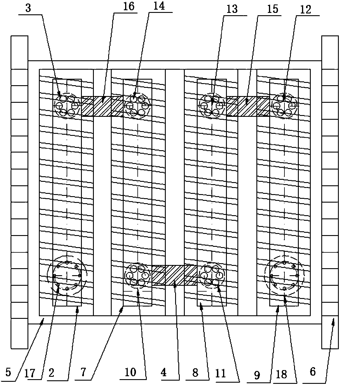
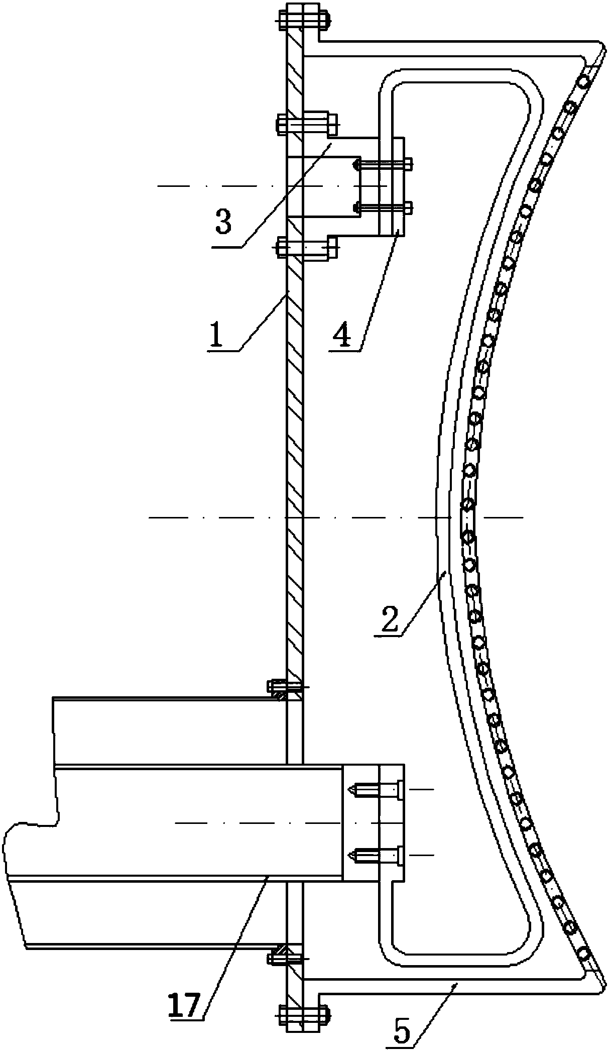
[0016] see figure 1 , 2 , a long ion cyclotron heating antenna with high tolerance to plasma changes, including a back plate 1, a Faraday shield 5 and four antenna current strips 2, 7, 8, 9, and the Faraday shield 5 is fixedly installed on the back plate 1 On the front side, the four antenna current strips 2, 7, 8, and 9 are respectively vertically and fixedly installed on the front side of the backplane 1, and are located between the backplane 1 and the Faraday shield 5, with a certain distance from the Faraday shield 5 , the four antenna current strips 2, 7, 8, 9 are connected in two phases through the jumper plates 4, 15, 16, and the feeding ends of the two outermost antenna current strips 2, 9 are respectively connected with radio frequency transmission lines 17, 18.

[0017] In the present invention, protective limiters 6 are respectively installed on both sides of the Faraday shield 5 .

[0018] The four antenna current strips 2, 7, 8, 9 are fixedly installed on the fr...


PUM


Abstract

The invention discloses a plasma-changing high-tolerance ion cyclotron heating long antenna. The plasma-changing high-tolerance ion cyclotron heating long antenna comprises a back panel, a Faraday shielding cover and multiple antenna current straps, wherein the Faraday shielding cover is fixedly arranged at a front side of the back panel, the multiple antenna current straps are vertically and fixedly arranged at the front side of the back panel and are arranged between the back panel and the Faraday shielding cover, the multiple antenna current straps are connected in series in a paired way via bridging plates, and feeding ends of the two antenna current straps arranged at the outermost side are connected with radio frequency feeding transmission lines. By the plasma-changing high-tolerance ion cyclotron heating long antenna, the coupling efficiency of the antenna can be substantially improved, the high-voltage standing wave on a power transmission line is effectively reduced, the influence of a large edge localized mode (ELMY) on a radio frequency emitter can be reduced, a high-constraint mode is enabled to be maintained, heating is more facilitated, so that the coupling efficiency of the antenna and plasma can be greatly improved, and the problem of striking of the high-voltage standing wave of the power transmission line is fundamentally solved.

Description

technical field [0001] The invention relates to the technical field of radio frequency power coupling of an ion cyclotron wave heating system, in particular to an ion cyclotron heating long antenna with high tolerance to plasma changes. Background technique [0002] Ion cyclotron resonance heating (ICRH) is one of the very effective auxiliary heating means in the tokamak device, which can directly and effectively heat the ions in the plasma. In the research of controlled nuclear fusion, in order to increase the energy in the plasma, the heating method of heating the plasma with high-power radio frequency waves is generally used. The ion cyclotron resonance heating system is an important plasma-assisted heating system on the Tokamak device (EAST) in my country. At present, the power of the ion cyclotron wave source on the EAST has reached 12MW. However, in the high power operation experiment, it was found that the high standing wave voltage on the transmission line caused th...

Claims


Application Information

Patent Timeline
Patent Type & Authority Applications(China)
IPC IPC(8): H01Q1/42H01Q1/50
CPCH01Q1/42H01Q1/50
Inventor 秦成明袁帅张新军赵燕平程艳王永胜
Owner HEFEI INSTITUTES OF PHYSICAL SCIENCE - CHINESE ACAD OF SCI
Why Eureka
Try Eureka