A construction method for foundation precipitation in underground pipe construction

A technology for foundation precipitation and construction methods, which is applied to excavation, waterway systems, water supply devices, etc., can solve problems such as difficult construction, silt at the bottom of the tank, and cumbersome equipment installation, so as to improve water collection capacity, water permeability, and increase The effect of seepage stability

Active Publication Date: 2019-08-09
LANZHOU UNIVERSITY OF TECHNOLOGY +1
View PDF4 Cites 0 Cited by
  • Summary
  • Abstract
  • Description
  • Claims
  • Application Information

AI Technical Summary

Problems solved by technology

However, the composition of the well point pipe method system is complex. Taking the commonly used light well point pipe as an example, the well point system consists of filter pipes, well point pipes, bent pipes, water collection main pipes, various pipe fittings and pumping equipment, dewatering equipment and materials. high demand
In addition, the construction of various well point pipe systems is also relatively difficult, and the installation of equipment is also relatively cumbersome. Both construction and operation have high requirements for organization and management.
Secondly, the current formulas for the water volume of various well point pipes are established under the assumptions of equal thickness, homogeneity, wide distribution of the aquifer, the level of the aquifer floor and the water table, and the stability of groundwater seepage, etc., which are generally equal to the actual engineering hydrogeological conditions. If there is a difference, this difference may bring certain errors to the related design calculation of the well point pipe system
[0008] For the buried pipe construction work close to the mountain, there will be pore water gushing out from the soil at the bottom of the trench adjacent to the mountain. After the water is drained during the day, there will still be interstitial water converging into the trench at night, causing the bottom of the trench to appear. Silty, if the normal foundation treatment is carried out, elastic soil can be formed, which seriously affects the construction quality of pipeline laying

Method used


Image

  • A construction method for foundation precipitation in underground pipe construction
  • A construction method for foundation precipitation in underground pipe construction
  • A construction method for foundation precipitation in underground pipe construction

Examples


Embodiment Construction

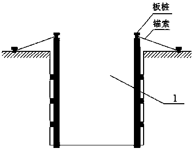
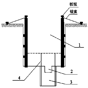
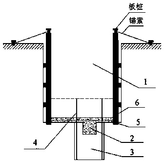
[0040] The engineering background of this buried pipe construction operation is the construction of a section of rain and sewage combined drainage pipeline with a length of about 6Km. The originally designed rain-sewage confluence pipe is a DN600HDPE double-wall corrugated pipe, with a design depth of 2.2m at the bottom of the pipe, and a socket-type hot-melt connection. The excavation depth of the pipe trench is 3.4m, using sheet piles to protect the wall, and the net width of the trench bottom is DN600+0.6m. The design of the ditch foundation treatment requires that the original soil with a thickness of 80 cm in the lower layer be tamped and backfilled in layers, with a compaction degree of over 95%, the middle layer of 30 cm thick lime soil should be replaced and compacted, and the upper layer should be a 100 mm thick sand cushion with a particle size of 8 to 15 mm.

[0041] The current problems encountered in the background project construction precipitation:

[0042] Som...


PUM


Abstract

The invention provides a pipe foundation dewatering construction method adopted during buried pipe construction. The pipe foundation dewatering construction method adopted during buried pipe construction comprises the links of digging a pipe groove and setting an auxiliary drainage channel, establishing a reversed filter layer I at the bottom of the pipe groove, installing a perforated collector pipe, establishing a reversed filter layer II on the upper portion of the collector pipe, installing a rainwater and sewage confluence pipe and an auxiliary structure of the rainwater and sewage confluence pipe, conducting plugging and mud jacking on the collector pipe, conducting soil covering and backfilling on the pipe groove and conducting ground recovery construction. An auxiliary drainage ditch, a water collecting well, double-side revered filter layers, a perforated collector tube are arranged at the bottom of the pipe groove, accumulated water of the pipe groove enters the collector pipe via the reversed filter layers and converge to the water collecting well, a submerged sewage pump is installed in the water collecting well and discharges water in time; and in this way, it can be ensured that buried pipe construction is conducted in a dry environment, and the construction quality of the buried pipe is guaranteed. The pipe foundation dewatering construction method is a construction dewatering technology which is applied to the construction environments not provided with well-point dewatering systems (such as a light well, a jet well, an electric osmosis well and a pipe well)and can meet the drainage demand. The pipe foundation dewatering construction method is simple and direct relatively and not complicated, the dewatering system design and construction quality are easily guaranteed.

Description

technical field [0001] The technical invention relates to a method for removing seepage water in pipe grooves in order to meet the requirements of pipe foundation treatment in the construction of buried pipes. In particular, it is a construction dewatering technology that meets the drainage needs in the construction environment that does not have a well point dewatering system (light well, jet well, electroosmotic well, tube well, etc.). Background technique [0002] Construction dewatering is an extremely important process in underground engineering construction. Reasonable design of construction dewatering organization not only has an important impact on construction quality and construction cost, but also affects the safety of structures. [0003] The main purpose of construction precipitation is: to provide a dry working environment for underground structure construction; to prevent water buoyancy from threatening the safety of underground structures during construction....

Claims


Application Information

Patent Timeline
Patent Type & Authority Patents(China)
IPC IPC(8): E02D19/06E02D19/08E02D17/04E02D19/10E03F3/06
CPCE02D17/04E02D19/06E02D19/08E02D19/10E03F3/06
Inventor 王少峰闫晓涛桂芳李慧莉胡家玮
Owner LANZHOU UNIVERSITY OF TECHNOLOGY
Why Eureka
Try Eureka